My time at Brooklands
1962 to 1971
By
Terry Rawkins
Copyright © 2024
I
Introduction
There follows a brief insight into my life from Secondary school in 1958 and my career up to 1971. Well that is the personal part but also here are facts and maps of the BAC aircraft factory at Brooklands, Weybridge around the year 1962.
Much of the data has been gleaned from a few leaflets and small books issued by BAC Publications.
To whom I am grateful.
Secondary School, Northmead Boys Guildford.
1958 at last in the school at the bottom of our garden but I still walked the long way round. The school had a large catchment area so a few new faces.
Woodwork and Metalwork but no Science, not enough teachers for our birth bulge.
Mr Senior was our form teacher an old boy in the traditional way ex army ex India. Teachers were English Mr Senior and Mr Goodman, Maths Mr Templeman Craft Mr Blackman, Geography Mr Todd, History Mr Strongman, Tech Drawing Mr James, Woodwork Mr Obee and Mr Day, Metalwork Mr Farley, PE Mr Hedges, Sport, Mr Senior. I played hockey because there was no football.
The first two years were OK as far as I can remember then the Thirteen plus, a sorting out the wheat from the chaff. I can't remember an exam just selection by classroom performance.
The new class was 3E, E for engineering. A small class all geared towards GCE exams. By now we had teachers for science subjects Mr Walker and Mr. Barratt. He was called Hairy, because he had longish wire like hair. The yobs would chant,"HAIRY HAIRY" in the playground. Funny that, this was just a few years before the Beatles and long hair.
In those days at that school our employment prospects were the local engineering firms Vickers, Dennis, Vokes, Drumond, RAE Farnborough or the forces, 3 GCE's was good, 5 unheard of so Uni or full time college was not the norm, that would come later with day release from work.
I enjoyed these days at school and did well in the subjects that I liked, 2nd in Science, near top in Maths but not so good in English, well spelling. Dr. Rawkins dictionary was mentioned by the teacher.
Our form teacher then was Mr Strongman, a great teacher, who had introduced us to his Chinese boy basher on our first day. Something we were meant to be frightened of. It perhaps shows my attitude then when I said, "But Sir, we have no Chinese boys here".
I had private teaching in Maths and Science from one of my Dad's colleagues, a Mr Evans who taught at Guildford Tech. He lived in Onslow village 3 miles or so away a hard uphill bike ride. That coaching did make a difference. I sat Maths and General Science O level at Guildford Tech and passed the Maths.
I had thought that I would like to be involved in the new up and coming electronics industry. I had made my first transistor radio from a kit.
My Dad was very supportive, I think I bought the kit from an advert in the Eagle comic. Dad's soldering iron was large, for lead work. I needed a small and more delicate version. So Dad went to see Mr. Martin along the road and came back with a lighted paraffin blow lamp with a fine soldering bit attached, not quite the thing. The next weekend he took me into work and someone showed me how to solder with my new small electric soldering iron. I took that radio on my "First class hike" with Tim Corbin.
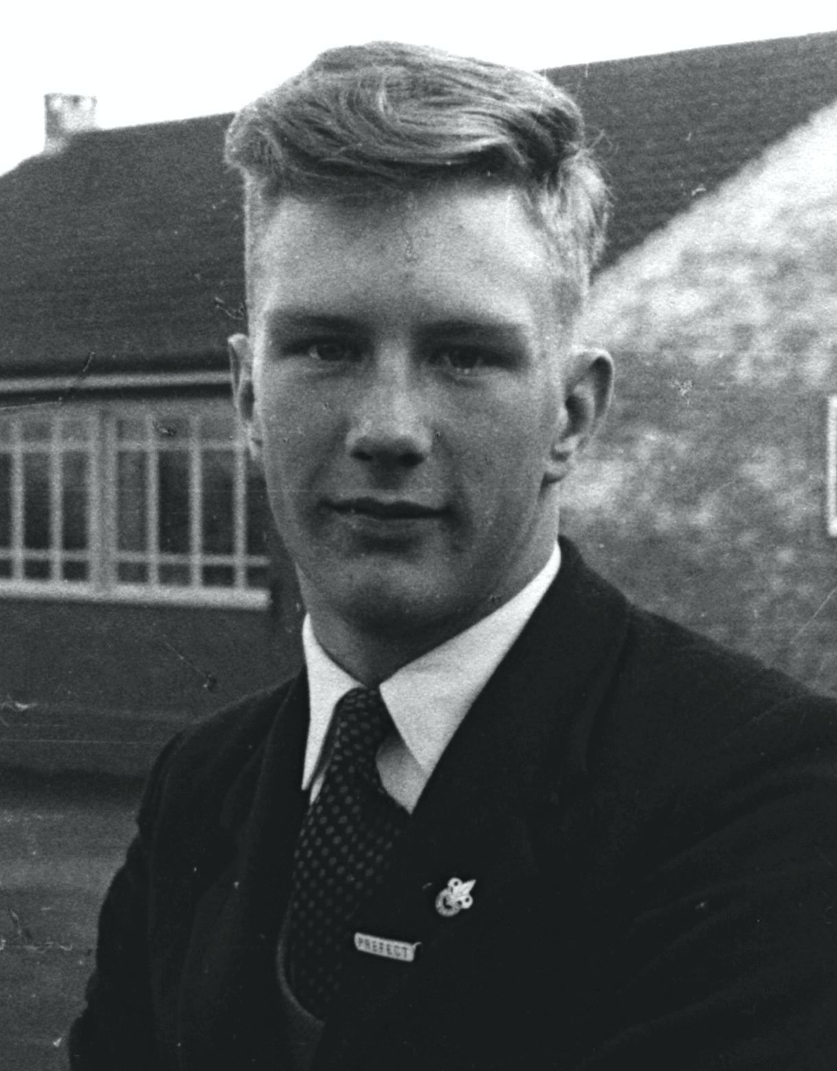
Born in September I could have left school at Christmas 1961 after my 15th birthday. It was thought better for me to leave in July 1962 thus enabling me to join a company as an apprentice. This was however a year before the course ended so I left with no exams taken.
I think it was Jan or Feb 1962 when I had my aptitude test and interview at Vickers. How I came out of that with a "Turner Skilled machinist" apprenticeship I will never understand but it was one of the many turning points in my life. Should I have stuck out for the electronics or did I find my niche?
Apprentice Training School
On 10 September 1962 I started at Vickers Armstrongs (Aircraft) ltd, soon to become BAC. Dad, who by now was the foreman of the production carpenters C1, would leave the house at 07:15. Pick up George M in the Avenue then pick up George Ide the machine shop foreman at Guildford Station. We would arrive outside the Carpenters shop at 07:45 and I would walk through the factory to the Apprentice School for 08:00. There were days when 07:15 was too early.
There was an intake of about 200 that year. Different grades; Craft, Technician, Engineer and Graduate. I was a lowly Craft Apprentice.
The school had a large workshop area with fitting benches and a machine tool area with Lathes, Milling machines, Shapers, Grinders etc.
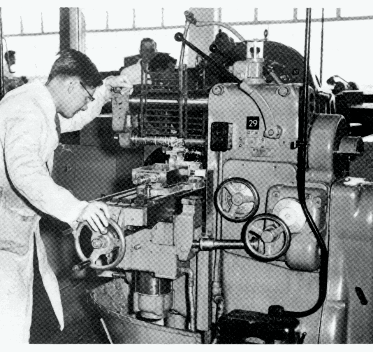
There were also, I think, three classrooms upstairs, here we learned about the theory of Flight and how to use our tools. Lightly oil when not in use, was the phrase of the day!
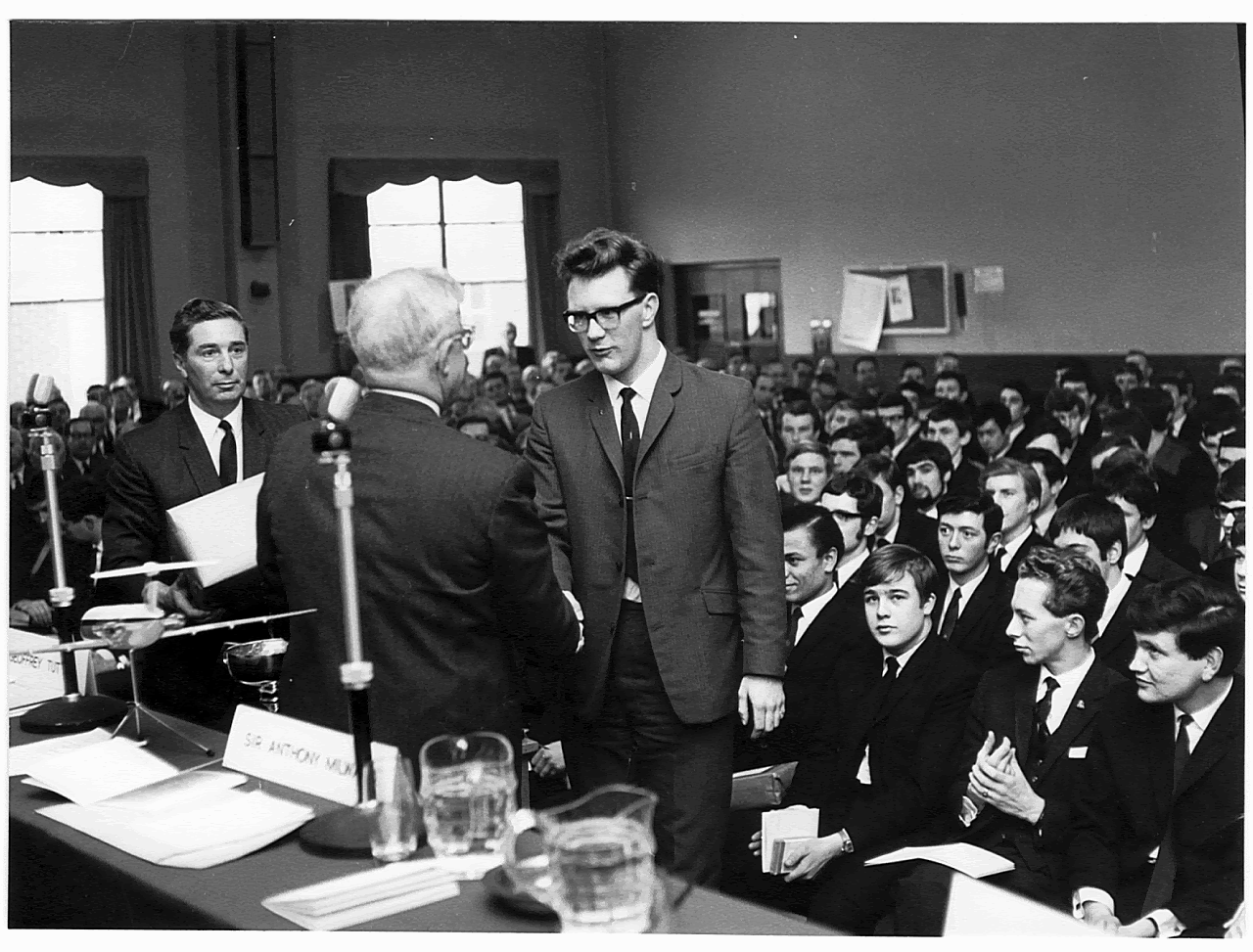
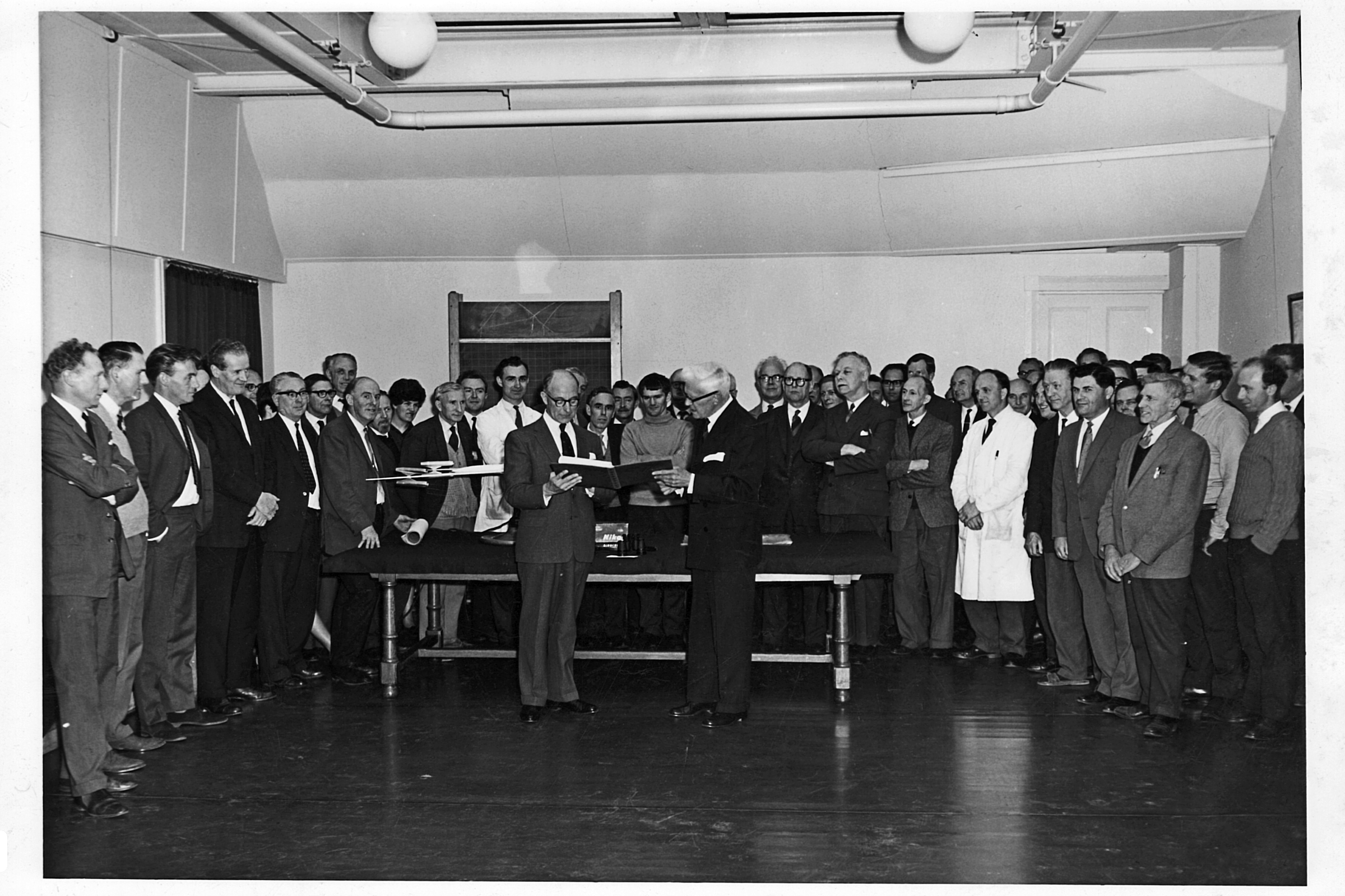
The head of the school was Jack Tyrrell; the previous picture shows him with the package I'm about to receive from Sir Anthony Milward. The Pam Newton Award as the best Craft apprentice of my year, 1967.
The training was good but looking back I can see that the system was stretched, both the Apprentice school and Brooklands College really did not know how to cope with so many students from the 1945/6 birth bulge.
We were, of course, a cash crop the government were paying the company (Grant / Levy)
An apprenticeship at Vickers (BAC) was very good with both practical and academic training. My apprenticeship lasted the normal five years but I was still attending college in 1970, eight years in all. My training, the type of work and those eight years at college were so useful to me in my later teaching career.
Research & Development
After two years in the training school, my targeted path was to visit each department in the factory; lathes and mills in the main factory machine shop this I was not looking forward to. Someone in the apprentice school thought that time in a specialist department would be better for me.
That is to stay the remaining three years in the same department. I was to go to the Instrument workshop of the R & D department. The work there was to support the ideas of Dr Barnes Wallis, at the time this was mainly swing wing aircraft but also, special plastic mirrors, TSR-2 and BAC-111 exciter systems.
I remember well going to see my new boss Peter Rogers. Grenville Scott, my instructor was with me. He had asked me to make the body of an air drill on one of the large lathes. About eight inches long by two inches diameter the work involved some intricate turning and boring plus I had to make an internal left hand thread !
The R & D workshop or Instrument shop was heaven, a small wooden building in front of the old Brooklands Pavilion. Clean with lino on the floor, each man had a purpose built work bench with two cupboards and two swing out quadrants to hold fine tools. So here I am, 18 years old, thinking how good I am, working on big lathes, in a workshop with small but expensive Swiss machines. Grenville tried to lift me by saying, "Terry has made a good job of the internal left hand thread". Peter rightly said an internal left hand thread is easier to make than a right hand.
My boss was Peter Rogers a superb engineer and craftsman.
There were 4 permanent staff there + one or two apprentices.
- One Watchmakers lathe made by Schaublin. Used by Peter Rodgers
- One lathe made by Schaublin. Used by Bob Parker
- One versatile Milling Machine made by Schaublin. Used by Terry Rawkins
- Two other lathes. Used by Jack Lowe, Syd Binstead
- And Two Myfords.
- All lathes had milling attachments
I am now thinking that some parts of that department were not so good. The whole R & D complex, our workshop, the carpenters shop, the design office, Jackson's shed, our own wind tunnel, and experimental areas, were all secret. There was a security guard at the front desk. I had to sign for the key most mornings.
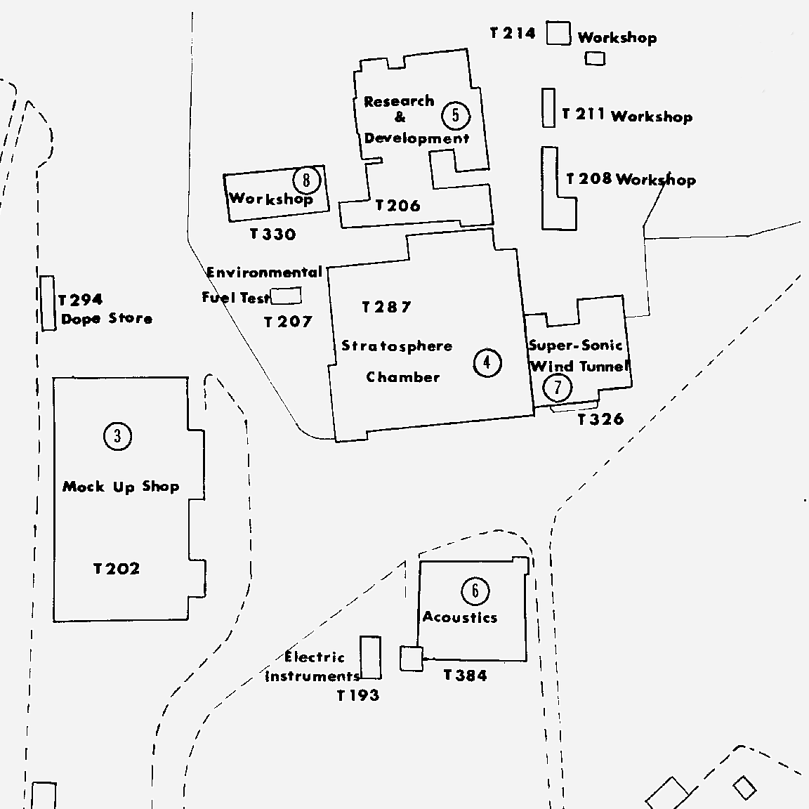
This did not encourage me to go looking and for three years I worked in that small building, T330 not going out at all.
The day would start at 08:00 the men would read the papers I would read a book until 08:30. My first machine was a small Myford lathe. This was the established amateur hobby lathe of the day but this one had all the kit; 3 Jaw chuck, 4 Jaw chuck, Collet chuck with inch collets, and a belt driven milling attachment. The main spindle could be locked with a pin and could be indexed in 24 places .
New jobs were placed on a table with the drawing and metal. Most were from the R & D drawing office for experimental rigs or projects some were from the production departments, these jobs were either too complicated or items that could not make any bonus money. Peter would divide the tolerance by 10, so if the drawing showed +/- 0.010" I had to make it better than 0.001"
One job required the 4 Jaw chuck but I found that one of the jaws had a split key hole on the jaws spindle. The next two maybe three weeks was spent making a new one. This involved turning the blank, cutting a square thread, making a square drift hardening and tempering it and using it to form the square keyhole. All made on the same machine to a high accuracy.
I moved to the Swiss milling machine when David left. Complex set-ups and more maths, great.
The work there was to support the ideas of Dr Barnes Wallis, in my time this was mainly swing wing aircraft but also TSR-2 and BAC-111 exciter systems.
A Swing Wing aircraft is unique as none of the services (Electrical, Hydraulic etc.) can be at the pivot point and so have to be carried in flexible articulated cables and pipes.
The workshop was involved with many swing wing projects over time :-
- Radio controlled flying models
- Ball Joints for the Hydraulics using a spherical turning attachment on the lathe
I made a four inch diameter twelve start Acme thread on the mill. This was part of the pivot cooling rig
An Aircraft Exciter is a device that shakes the aircraft to test where any critical vibrations occur.
The TSR-2 exciter had a very dense metal piston some 2" dia and 18" long which was moved back and forth at great speed.
I ripped my trousers lifting the piston it was so heavy. I had to strip the thing down, the PTFE coating was checked and I built it back up.
BAC 1-11 exciter had servo motors that moved the aircraft's control surfaces.
All this was cutting edge in the 1960's. Other work was carried out on :-
- The new Plastic Mirrors, I made a dental mirror jig
- A model of a BAC-111 medical evacuation aircraft
- Some work on Submarines.
As I write this today in 2024, more than 50 years on, I have to think how different it is now. Carbide tools that you do not, can not sharpen and maths on a calculator / computer / spreadsheet
The 13 x 9 Wind Tunnel
In August 1967 I was about to finish my apprenticeship in the R & D workshop. I was advised to think about my future and the future of R&D, based on the age of Barnes Wallis. The training school administration could move me whilst I was still an apprentice but it would be difficult thereafter. I had two options; the wind tunnel workshop or the up and coming Numerical Control section of the Design Office. A landmark decision!
Just before my 21st birthday I represent BAC at the Industrial Society's Apprentice Conference at Kebel College in Oxford. An interesting week and a large mix of cultures!
I stayed in the wind tunnel workshops for four years during which I still pursued my day release at college, (Full Tech Cert) and started a maths degree at the OU.
The Wind Tunnel machine shop had to take on a variety of tasks with a high standard of work and precision making both the model aircraft and support instrumentation for the tunnel. Many of the machine tools could be described as ground breaking with early Spark erosion machining and a large NC vertical milling machine.
Two machines that I had some fun operating were:-
A home grown 4 axis NC milling machine
The task was to cut a groove along the leading edge of a 1/6 th scale Concorde wing. Yes it was big, the groove was to take a heating wire to melt the ice in a cold wind tunnel in France and see where the ice travelled. The wire / groove had to be an even distance from the wings surface which was, of course, a very complex shape.
The machine was based on a reconditioned G sip jig borer used as an inspection machine. I would set the Y axis and the milling head (called the MED Head) would move the cutter in the Z axis and rotate in the A axis (about the X) . The machine would move in the X axis under my control which would drive a paper tape reader. It was this paper tape that held the instructions for the Z & A movement, one hole in one of the four tracks would fire a solenoid that moved either +Z, -Z and/or +A, -A. The electronics for all this was valve driven, it was only 1970!
The sharp end of this machine was a specially shaped cutter to cut a groove with a large chamfer that would carry the wire which was then covered over with a filler.
Latter on the same machine was used to shape the leading edges of a BAC1-11 model. Here the cutter was conical in shape, think large countersink. Again the head would "roll around" the work piece at the same time as travelling in the X and Z axes.
When in "Inspection Mode" the machine would be used to measure the position of pressure plotting holes in the wings of the models. Somehow I got involved here when it came to measuring wing profile shapes.
The normal head would have a microscope whose depth of field was only 0.001" . That is if you looked down onto a ball you would see a ring in focus, not the full ball.
I would move the head to a given X,Y location look down the microscope until the metal came into focus and write down the height of the Z axis.
Those pressure plotting holes were 0.004" in diameter and drilled on one of two high precision Swiss made G-sip jig borers. There were 6 operators on these two machines over 3 shifts each day 6 days a week. Bill, John, Ray, Geoff and I worked a double day shift 06:00 to 14:30 and 14:00 to 23:30 and Ted worked on nights 23:00 to 06:00.
G-Sip 6 Jig Borer John and I worked together, John on the large 7A machine and me on the smaller 6A. Both machines could split a micron (0.001 mm)
The 6A was metric and was purchased in 1970 for £25,000 (In 1969 I bought my first house for £4,300, now £500,000) I have seen a modern version of the same machine priced at £2,000,000
Both machines had a large (800 mm diameter) Rotoptic rotary table this could split 1 second of arc. On the top of this was very often placed a large tilting rotary table.
One task of note was the cutting of a spherical bore. We started thinking about co ordinate cutting. The DO chaps tried the new MiniMop computer system but somehow it was left to my foreman, Colin Bell, digging out an old book and letting me get on with it. You had to set the tilting rotary at an angle such that the tool bit in the boring head did not quite make a 360 degree cut ie cutting mostly metal but some air. The cut was made with the boring head rotating and me winding the rotary table a full 360. I do remember Ted calling me a cheeky young whipper snapper (A young and inexperienced person considered to be presumptuous or overconfident.) OK I will take that now but then I was cross because he had nearly wrecked the job with a form tool ignoring my set up and calculations completely. Ted was on permanent nights. They would work until 02:00 or so then get some sleep. Waking at 05:00 for the last hour. Working like this errors could occur, I would know if the job had gone wrong, it often did, if I had an apple on my toolbox.
I left the Wind Tunnel and BAC in 1971. My working life ended in 2003 when I retired from my job as the Senior Lecturer in charge of a CAD / CAM department in a college of FE. In 2004 we moved to our home on the Isle of Wight.
SIP Hydroptic Jig Borers
Societe Genevoise d Instruments de Physique
Introduced in 1934, the heavily built and weighty Hydroptic range was designed for use both as a precision production milling machine and a jig borer.
Hydroptic machines were not fitted with conventional table-drive feed-screws, instead (as the model name suggests) they used a smooth-moving, very precise hydraulic system. Thus, lacking any means of determining table travel by reference to a rotating screw and micrometer dial, they were fitted with same system used on the much smaller No. 1-H and 2P models - highly accurate standard scales of the type used to calibrate other measuring equipment in national testing organisations.
The scale graduations were illuminated, magnified and projected onto a glare and parallax-free reading screen. This easy-to-use, absolutely reliable arrangement (it was entirely optical with no wearing parts) allowed readings to be taken down to 0.0001" (0.001 mm) - an astounding degree of precision for such large machines - with Societe Genevoise d instruments de Physique also guaranteeing an accuracy for all displacements of work-table and spindle head of 0.00015" (0.003 mm) on the 6A and 0.0002" (0.005 mm) on the 7A.
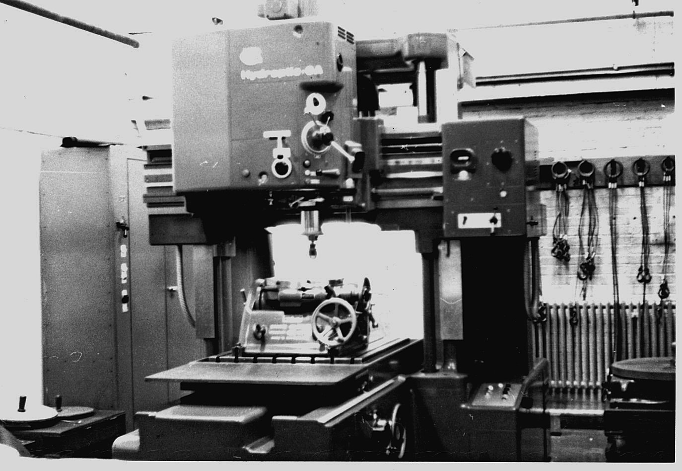
6A specification:
Table 43.25" x 33" (1100 x 842 mm)
Table travel 40" (1000 mm)
Head-saddle transverse travel 28"
The Apprentice Training School
From the Visitors Handbook :-
Lectures, practical workshop and machine experience and apprentice administration are the activities centred on the well equipped Apprentice Training School building opened in 1955. Comprehensive schemes are in being for the training of Trade, Engineer, Undergraduate and Post-Graduate apprentices.Training is designed to achieve a balance between practical experience gained in the Apprentice Training School, the shops and technical offices of the Company and theoretical training at Technical Colleges or Universities. The future of the Company owes much to the soundness of the Apprentice Training schemes. Basically, the problem may be reduced to the bringing forward of a balanced supply of skilled men trained to meet the foreseeable needs of a decade or more in the future, in an industry of rapid technical advance.
The present apprentice population (mid 1962) is about 500. Demonstrating the intense competition for apprentice training is the fact that the ratio of enquiries to acceptances is of the order of 15 to 1.
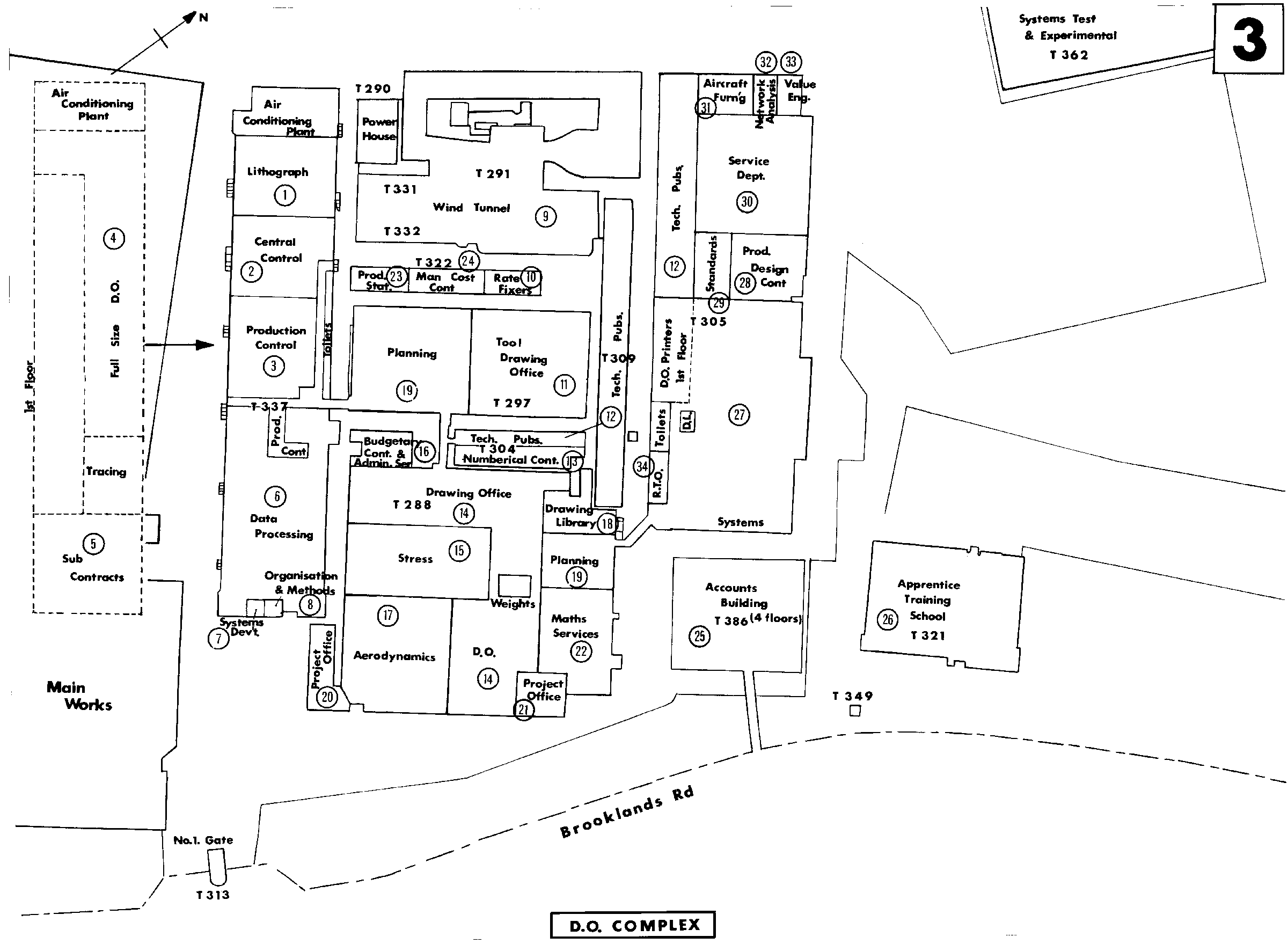
The Aircraft Design Organisation
of Vickers-Armstrongs (Aircraft) Ltd.,
Has its headquarters in the Design Office at Weybridge, which is one of the largest buildings of its kind in Europe.
Over 1,000 people work under its roof. The Design Office itself is laid out on the open plan principle, emphasising that the finished design represents the combined efforts of many departments.
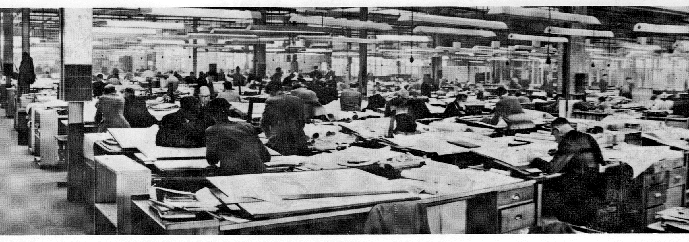
Design Work normally begins in the Project Office, virtually a design organisation in miniature, where the relative merits of alternative schemes are evaluated.
Within the Design Organisation are sub departments dealing with specialised subjects such as :-
- (17)Aerodynamics,
- (15)Stress,
- Structures,
- Weights
- Airworthiness.
- The Mathematical Services Department,
- Mould Loft,
- Wind Tunnel
- Aircraft Laboratories
- (1)T 337 Lithograph
- (2)T 337 Central Control
- (3)T 337 Production Control
- (4)T 337 Full Size D.O. (lst Floor)
THE MOULD LOFT is responsible for supplying the production departments with full-scale working drawings , based on designs issued by the Drawing Office, Many of the basic production drawings used by the shops are reproduced by the Mould Loft on metal, for precision, by the most modern methods of photographic and lithographic printing, The Mould Loft has the important function of "fairing" the overall lines of the entire aircraft in accordance with the parameters established by the Project office and Aerodynamics Department.
- (5)T 337 Sub-Contracts (lst Floor)
- (6)T 337 Data Processing
- (7)T 337 Systems Development
- (8)T 337 Organisation & Methods
- (9)T 291 Wind Tunnel
- (10)T 322 Rate-fixers
- (11)T 297 Tool Drawing Office
The Jig & Tool Drawing Office works in parallel with the Design Organisation from the start of a new project. As aircraft today are placed in series production from the outset, without the manufacture of hand-built prototypes , it follows that jig and tool design is a first step before construction can begin. The requirements for good quality components with the maximum degree of interchangeability calls for high quality jigs and tools. With the increasing size, refinement and complexity of aircraft, leading to higher production costs , it is necessary to obtain the maximum output from the minimum number of jigs and tools, without sacrificing quality, The ingenious solutions to these apparently conflicting requirements can be seen in every production shop in the factory.
(12) The Technical Publications Department has two main functions: the production of aircraft manuals and the supply of spares provisioning data. Aircraft manuals are written and illustrated to conform to the British Civil Airworthiness Requirements and form part of the documentation necessary for the granting of a Certificate of Airworthiness. Manuals are prepared generally in accordance with the A.T.A, 100 Specification and are certified as meeting the requirements under the Vickers-Armstrongs Design Approval. One set of Vanguard manuals comprises forty volumes and include some 4, 500 illustrations.
Spares provisioning data are prepared and forwarded to all airline operators, advising them of the spares required to maintain their fleet during, normally, the first year of operation. This information is supplied progressively and completed approximately one year in advance of the first aircraft delivery in time for the parts to be ordered, manufactured and delivered concurrently with the aircraft.
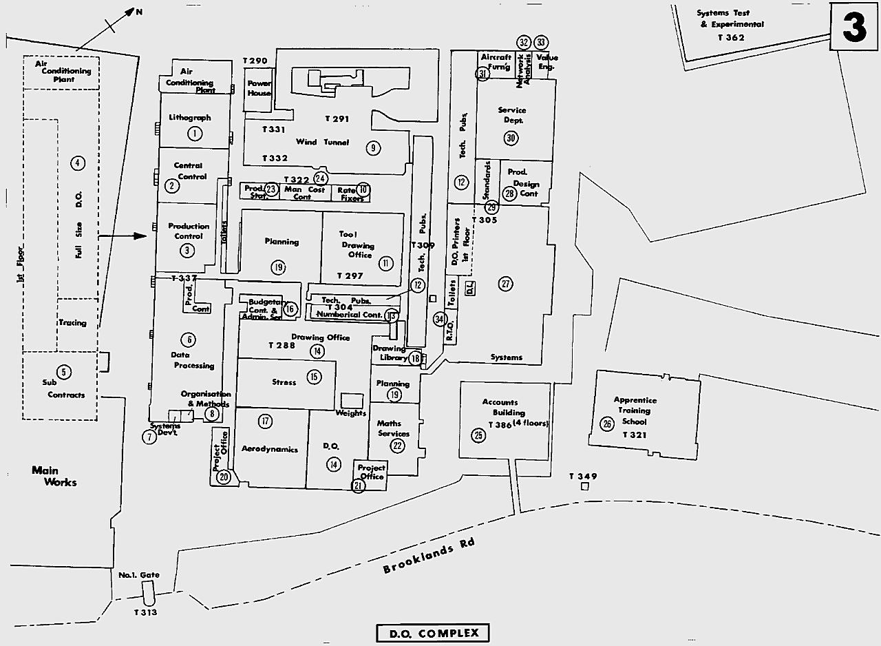
- (13)T 304 Numerical Control
- (14)T 288 Drawing Office
- (15)T 288 Stress
- (16)T 288 Budgetary Control & Admin. Services
- (17)T 288 Aerodynamics
- (18)T 288 Drawings Library
- (19)T 288 Planning
- (20)T 288 Project Office
- (22)T 288 Maths Services
The Mathematical Services Department uses analogue and digital computers to assist the Design Organisation in a variety of ways. With the aid of the analogue Computer, for example, it is possible to simulate the response of an aircraft and its control system to the loads experienced under a wide range of operational conditions. The digital computer, with its ability to perform arithmetic at superhuman speed, solves problems for the aerodynamics, stress, flight test and other departments; airline route and cost analyses are among its many functions.
- (23)T 322 Production Statistics
- (24)T 322 Manufacturing Cost Control
- (25)T 386 Accounts Building
- (26)T 321 Apprentice Training School
- (27)T 305 Systems
- (28)T 305 Production Design Control
- (29)T 305 Standards
- (30)T 305 Service Department
- (31)T 305 Aircraft Furnishing
- (32)T 305 Networth Analysis
- (33)T 305 Value Engineering
- (34)T 305 Resident Technical Office
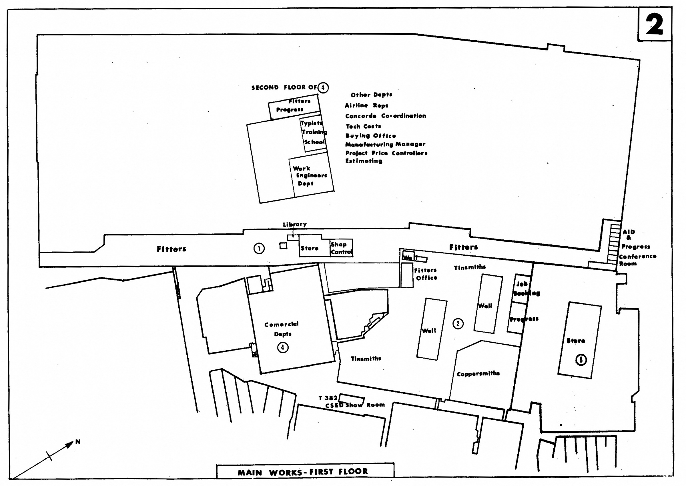
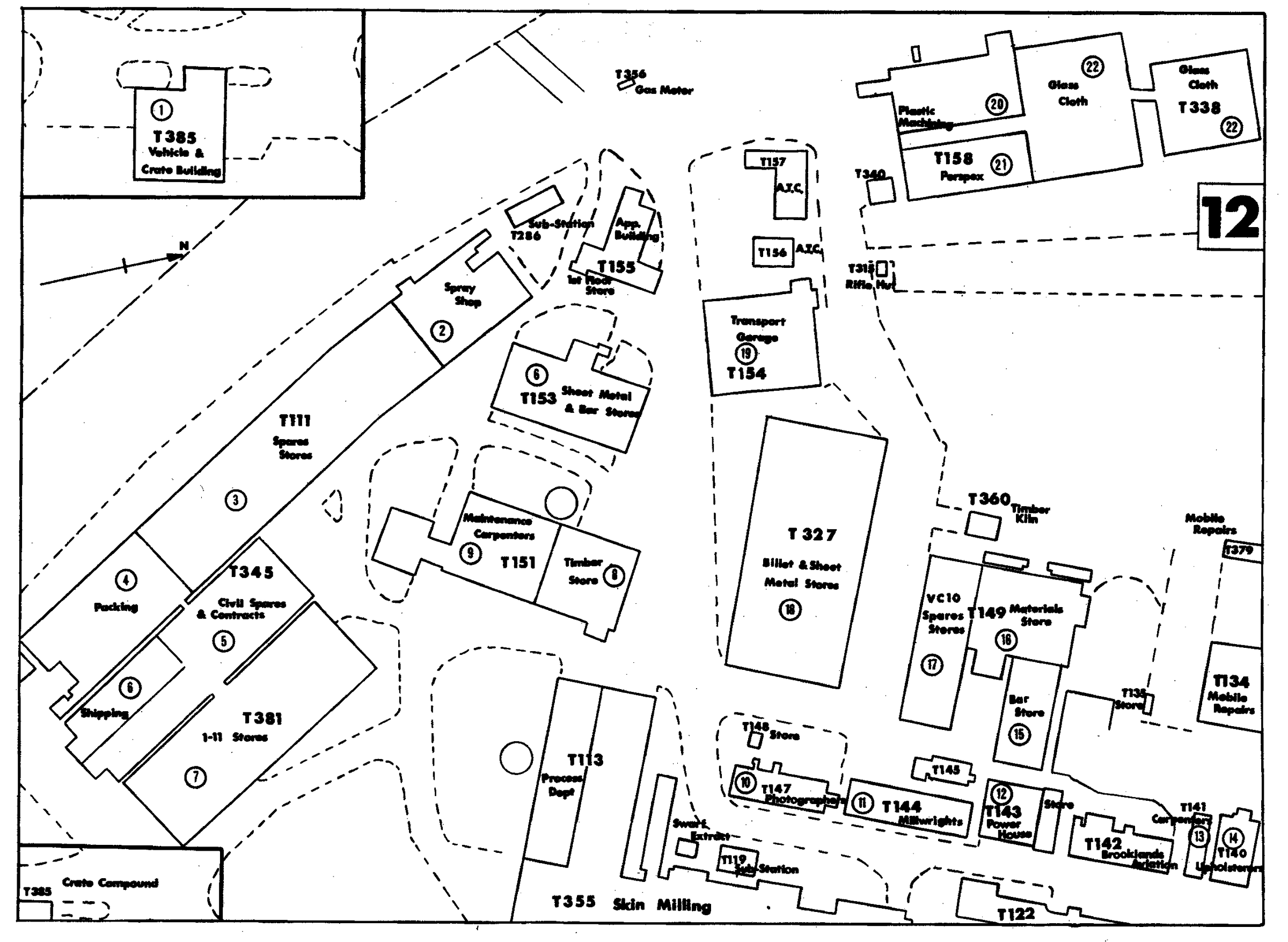
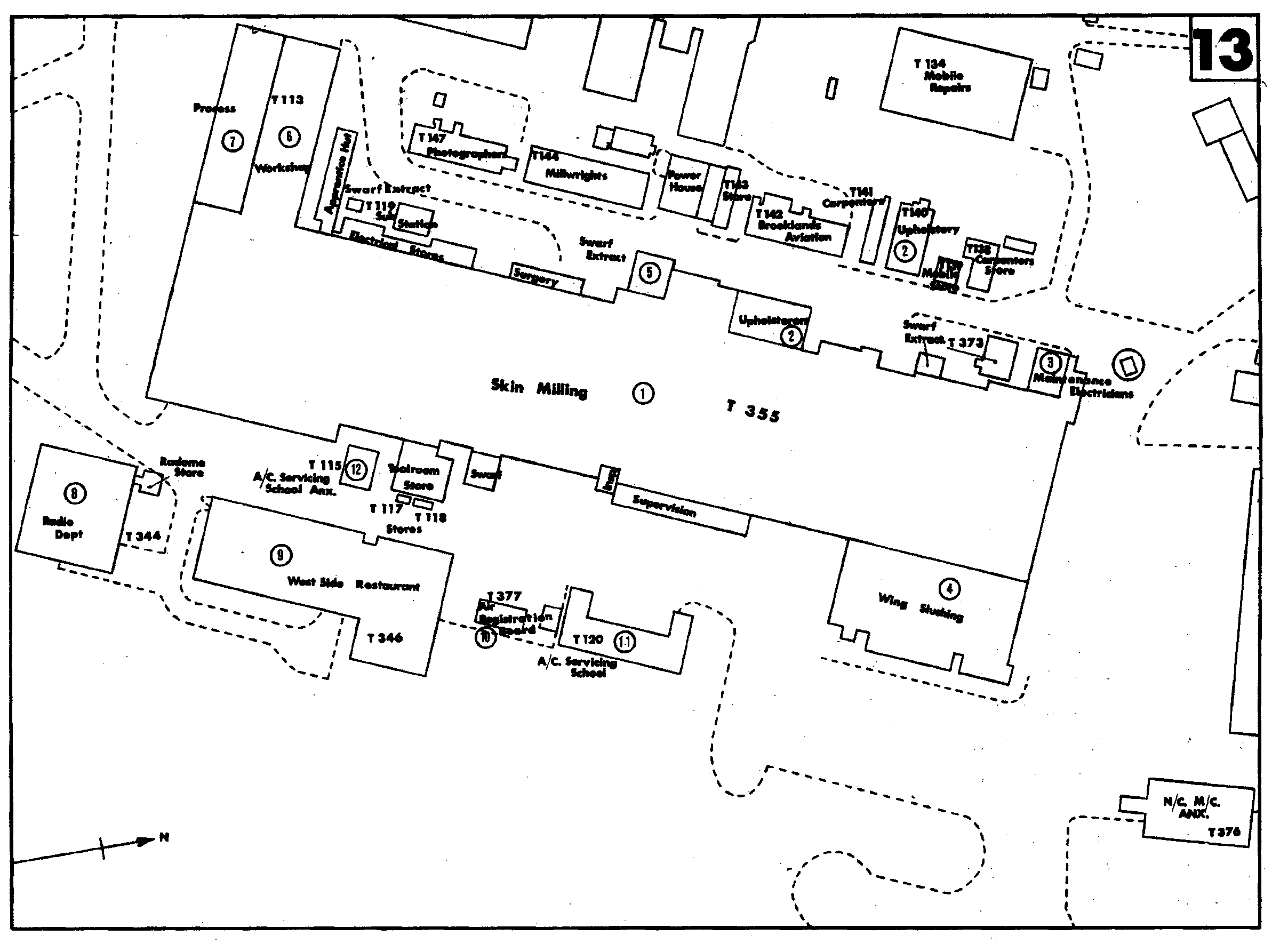
The Main Works
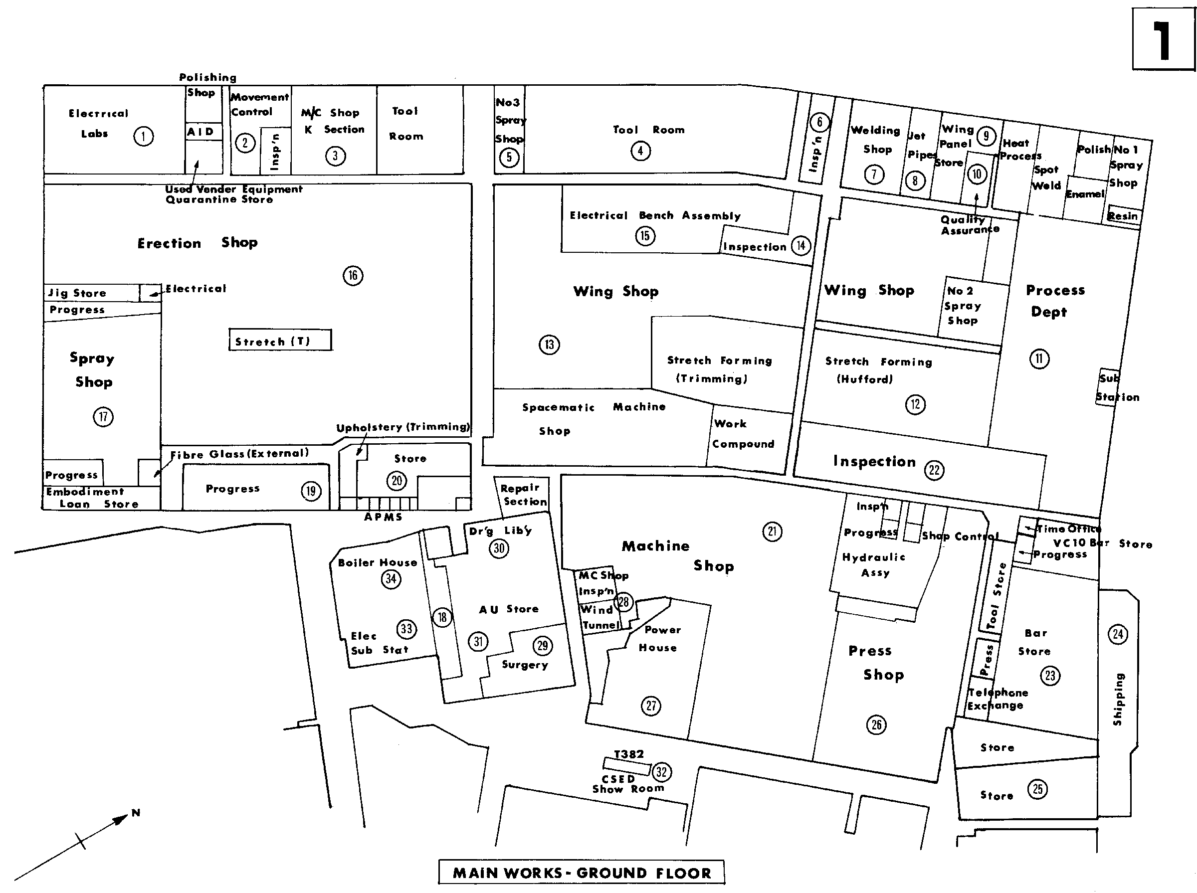
The various departments within the main works are listed below:-
- 1 Electrical Laboratories
- 2 Movement Control
- 3 Machine Shop "K" Section
- 4 ToolRoom
The Toolroom represents the transition from design to production the first stage in the cutting or forming of metal. Before aircraft parts can take shape the necessary tools must be made; this is the responsibility of the Toolroom, whose work covers 150 classes of tool, ranging from a small routing template to a multi-ton, 60 ft. long VC-10 wing assembly jig embodying some 4,000 detail parts. Within this wide range the Toolroom produces some 300 - 400 tools, monthly, together with interchangeability gauges to ensure that major Components produced from separate jigs are identical. The Toolroom uses a variety of some 70 different types of machine, the largest being a Hypro fourhead milling machine of 12 ft. capacity. Recent work of this department completed the massive jigs on the VC-10, it is now busy with those of the Super VClO and the One-Eleven.
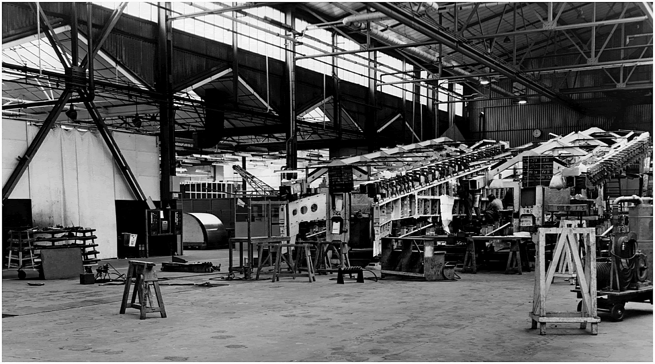
The rectangular box section steel frameworks for these jigs are of relatively simple construction, but the detail fittings within them involve intricate machining operations and are located to tolerances of 0.001 in. with the aid of optical setting equipment.
The Toolroom is also responsible for maintenance of jigs and fixtures, erection of test structures and manufacture of lifting gear and trollies. Apart from the work of the Toolroom, specialised tool manufacture is also carried out within such departments as the Fitters, Machine Shop, Press Shop, Tinsmiths and Carpenters.
- 5 NO. 3 Spray Shop
- 7 Welding Shop
- 8 Jet Pipes
- 9 Wing Panel Store
- 10 Quality Assurance
- 11 Process
The Process Department is concerned principally with heat treatments and anti-corrosive measures, from the time the first metal is cut until a complete, painted aircraft is rolled out for first flight.
During manufacture of the detail parts the Process Department undertakes the normalising of light alloys , all necessary heat treatments on steels, plating and nitrogen hardening where required. Chromic anodising is used extensively on bar stocks for crack detection purposes. Supplanting chromic anodising as a protective treatment is the Alocrom 1200 process which is simpler and has a greatly reduced processing time.
The normalising and Alocrom plants are the largest in Britain designed to handle the biggest VC-10 and Vanguard components. The department also handles dye pentrant crack detection on forgings, stampings and finished machined components, all the operations described so far are pre-treatments or inspection, the visible part of the departments work on a completed aircraft being the paint finishes.
The VCl-10 is painted throughout internally and externally. The external paint alone weighs about 250 lb, per aircraft, but this protects the aircraft from corrosion, reduces the cost of cleaning and virtually eliminates scratch damage. Application using epoxy resin based paints is carried out by stoving or air drying in strictly controlled conditions. Modern spray booths, strategically sited around the works, accommodate components up to complete Vanguard fuselage size.
The most recent examples are the versatile stretch wrap forming and rotary stretch forming machines, designed by the Toolroom at Weybridge.
The Inspection Department exercises quality through every stage of aircraft manufacture using the most modern inspection methods. Non destructive testing techniques including ultrasonic testing, X-rays and dye penetrates play a vital part in ensuring the integrity of modern aircraft structures which use an increasing number of machined components.
Another modern facet of the Company's inspection methods concerns the functional testing of production systems components, and indeed complete systems, before installation in the aircraft on the production line.
The final phase of production begins with the delivery of the fuselage shell to the erecting shop, where wing and tail surfaces, undercarriage, power plant and systems are added.
The total final assembly space available at Weybridge, Hurn and Wisley is some 900,000 sq. ft, , and the combined length of all assembly lines at peak production exceeds one mile.
- 17 Spray Shop
- 18 Embodiment Loan Store
- 19 Progress Department
- 20 Store
- 21 The Machine Shop
Using a range of 240 machines, produces some 2,000 components per month, ranging in size and complexity from pins, bolts, spindles and hydraulic valves to complete undercarriage assemblies. (Vickers differs, incidentally, from many aircraft manufacturers in designing and building its own undercarriages).
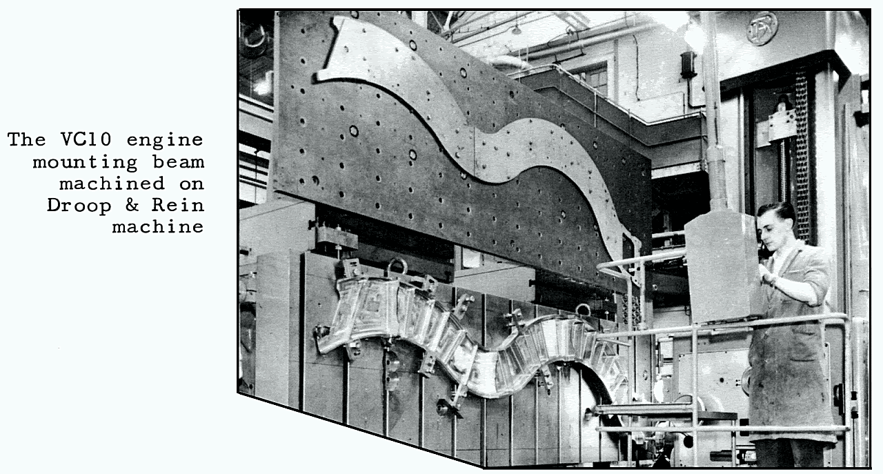
The trend towards larger components, made in steel rather than Dural, is reflected in the Machine Shop including four Droop and Rein electric profiling machines the only such equipment used by the British aircraft industry, Their role is to produce VC10 engine and undercarriage support beams; the latter are 340 lb. high tensile steel components which are machined from 1 ton billets.
Also used in the Machine Shop are jig borers which feature automatic control by punch cards or punch tape.
- 22 Inspection
- 23 Bar Store
- 24 Shipping
- 25 Stores
- 26 Press Shop
The Press Shop is responsible for forming a wide variety of aircraft details in sheet alloy or steel, ranging in size from a small washer to a 35 ft, long machined fuselage skin panel for the VC-10. Its output of components is 6-8,000 per month, The range of 160 machines used in the Press Shop extends from hand presses and folding machines to the 2,600 ton rubber press; the Hydroform press (the only machine of its kind used by the United Kingdom aircraft industry), which can apply pressure up to 15,000 lb/sq.in. and can form steel components 1/2" thick; drop hammers; and the 300 ton mechanical press used to form VC-10 and One-Eleven sculpture-milled fuselage panels.
- 27 Power House
- 28 Machine Shop Inspection & Wind Tunnel
- 29 Surgery
- 30 Drawings Library
- 31 AU Store
- 32 CSED Show Room
- 33 Sub Station
- 34 Boiler House
- 35 VC-10 Bar Store
T206 Brooklands Clubhouse
From a page in the booklet "Test or be damned".
Published by Vickers-Armstrongs(Aircraft) Ltd. C 1962
Department of Aeronautical Research and Development
Swallow, the first variable geometry design, the "Dam Buster", "Tall Boy" and "Grand Slam" (earthquake) bombs, and Geodetic construction are but three of the inventions produced by Dr.B. N. Wallis and his team, who form our Department of Aeronautical Research and Development.
Their purpose is threefold:-
To act, when requested, as consultants in the field of design, development, and production;
to devise and produce specialised testing equipment of a standard and quality that cannot be purchased (e.g., the Stratosphere Chamber and Supersonic Tunnel);and to invent novel ways for solving perennial and future problems in a practical and economic way.

At the time of writing they are developing apparatus for the BAC One-Eleven flight resonance programme. A cheap, easily made, ultra lightweight mirror, which does not mist up or shatter, is another invention which they have recently developed. Aeronautical Research and Development endeavours to be a completely versatile department that leaves nothing outside its province.
The R & D was the birthplace of a number of renowned World War II weapons, including the "Tallboy" bomb and the "Dam-busting" device. Since the war it has been largely concerned with development of the Swallow variable Wing geometry project, of which little information has been published.
Attached to the Department is the Stratosphere Chamber, which is used for large-scale environmental testing of a wide range of aeronautical and other products, The Chamber has a diameter of 25 ft. and is 50 ft. long, The altitude range of the Chamber is 0 - 80,000 ft, and temperature can be varied from -65°C to at least +55°C.
Such conditions as wind, rain, blizzards and solar radiation can be simulated in the Stratosphere Chamber so that when time permits a considerable amount of work for other organisations is undertaken.
The Chamber is also used to Operate the supersonic intermittent wind tunnel, which Connects the Chamber to a 30,000 cubic: ft, air reservoir. Speeds of Mach 1,4 to Mach 3, 5 are Obtained in the tunnel for short periods by the simple method of exhausting air from the Chamber and replacing it from the air reservoir.
The Stratosphere Chamber
From a page in the booklet "Test or be damned".
Published by Vickers-Armstrongs(Aircraft) Ltd. C 1962
The high-altitude test chamber was designed by our Aeronautical Research and Development Department to enable tests to be carried out under conditions of extreme cold and altitude. The required temperature, humidity and pressure can be maintained almost indefinitely and varied at will to produce snow storms, icing and other meteorological phenomena likely to be encountered.
All this can be superimposed on the actual pressure differentials which the fuselage of the aircraft will undergo on a typical commercial flight. Thus a very close approximation to the severest flight conditions can be repeatedly imposed on the aeroplane under the eyes of our test engineers. Similar tests can be carried out on components and equipment.
The chamber consists of an insulated welded steel cylinder 50 feet long and 25 feet in diameter. The chamber is "fed" by vacuum pumps, and has refrigeration and humidity control equipment. The pressure range is from sea level to 80,000 feet and temperature range from -65°C. to at least + 55°C. Initial rates of Climb vary from 1,500 feet per minute with the chamber air at + 55°C. to 1,000 feet per minute at 60°C.
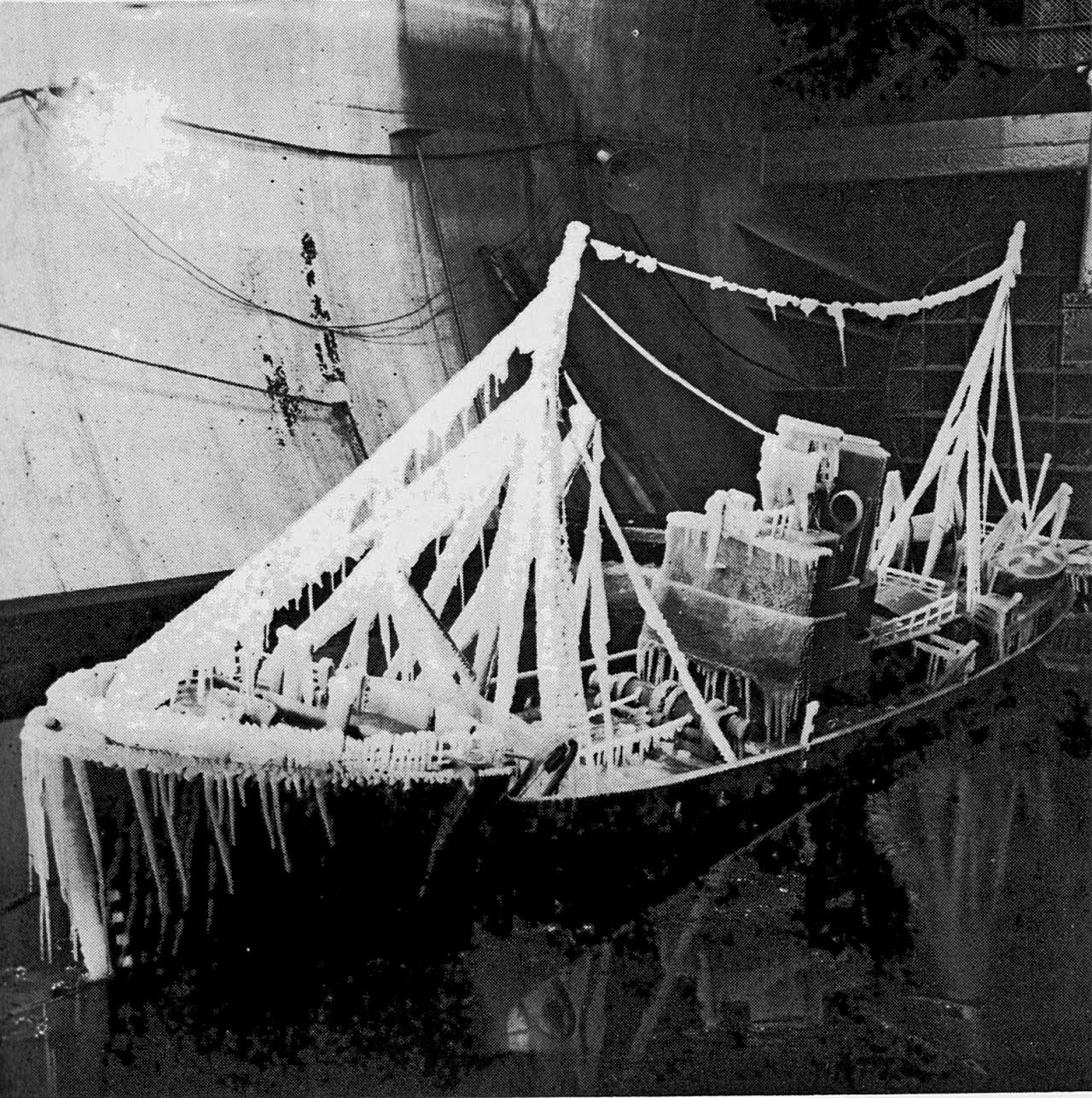
This unique facility, the largest of its kind in the world, has been used in several fields besides aviation. On January 25th, 1955, two trawlers, the Lorella of 558 tons and Roderigo of 810 tons, were lost with all hands, north of Iceland. Tests carried out on a l/12th scale l7ft. long model, of the trawler Kingston Garnet, showed that under Arctic conditions ice formed on the rigging to such an extent that the weight caused the trawler to capsize.
The supersonic wind tunnel
From a page in the booklet "Test or be damned".
Published by Vickers-Armstrongs(Aircraft) Ltd. C 1962
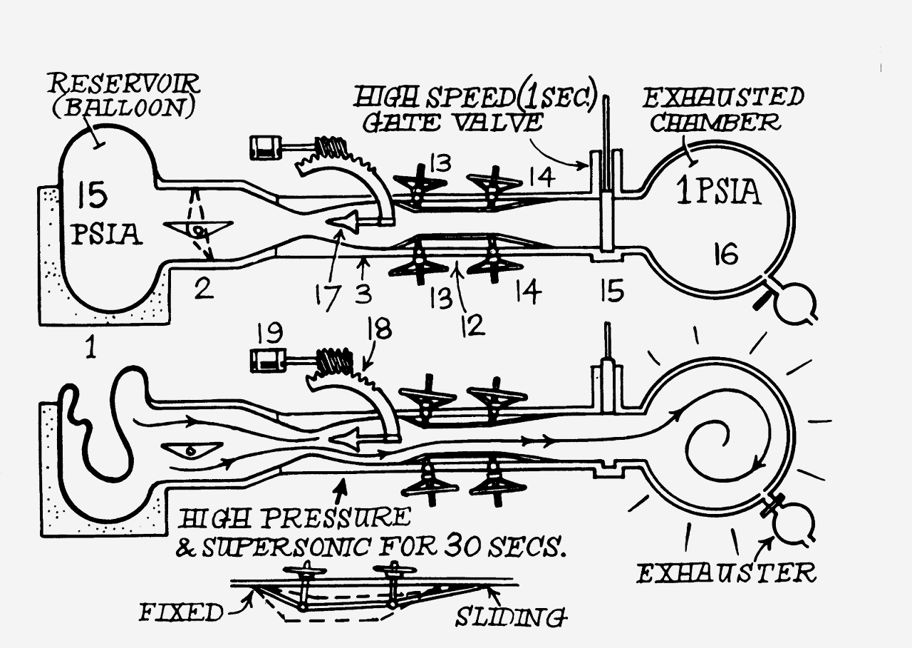
The supersonic tunnel, which was designed by the Aeronautical Research and Development Department, has a 20in. square working section. The operating principle of the tunnel is to evacuate the stratosphere chamber (a Convenient low pressure source) to as low a pressure as possible.
The tunnel, which consists of an intake, working section and diffuser, is connected to the stratosphere chamber through a quick opening valve. When the latter is sprung open, air is sucked in through the tunnel to fill the vacuum in the chamber. Supersonic is caused by a convergent-divergent nozzle made from a pair of detachable, profile, liners. The shape of the nozzle governs the Mach number produced in the working section; thus the Mach number can be altered by using liners of differing profile.
The duration of a run in this tunnel varies from 20 seconds at a Mach number of 1.4 to about 30 seconds at Mach 3.5 (2,700 m.p.h.) and a test run can take place every 15 minutes (the time required to evacuate the stratosphere chamber). The tunnel is electronically instrumented so that the three component forces and three moments acting on a model can be recorded automatically, for a complete range of aircraft incidence during the one test run.
Upkeep - The Bouncing Bomb
Upkeep was the codename for the weapon developed for the Dams Raid carried out by 617 Squadron Royal Air Force on the night of 16/17 May 1943.
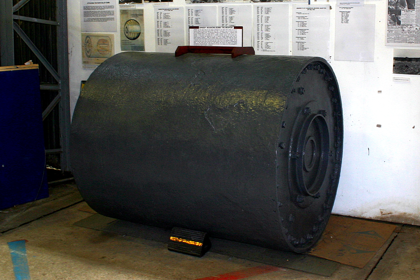
Technically it was not a bomb but could more correctly be called a mine. The Germans described it as a 'Rotating Mine'.
It weighed 9,250 lbs and contained 6,600 lbs of Torpex explosive. It was a cylinder 59 7/8 ins long and 30 ins in diameter. It was carried in the bomb bay of a modified Lancaster bomber, with its bomb doors removed, in a mounting best described as a pair of vertically mounted callipers which could be opened laterally to release it. Within the callipers were a pair of wheels which fitted into circular tracks at each end of the weapon so that it could be rotated backwards at 500 rpm. This was done by a hydraulic motor at the front of the bomb bay with a belt drive to the starboard wheel.
On the opposite side were three holes to take the hydrostatic fuses to set off the bomb at a predetermined depth. In their centre was the hole for a self destruct fuse should the weapon be dropped inadvertently or the aircraft crash.
The Weybridge Tunnels
There follows text from the booklet "Test or be damned".
Published by Vickers-Armstrongs(Aircraft) Ltd. C 1962
Mach 1.4 to 3.5 is the operating range of the supersonic tunnel, the other four covering subsonic speed's.
The 4ft. low speed tunnel, the 4ft. referring to the width of the working section, was built in 1916 and was the first commercially owned tunnel in the United Kingdom. Apart from Calibrating flight test equipment (eg. pitch and yaw meters), it is not in extensive use today.
The 8ft. low speed tunnel came into use in 1931 and was modernised in 1956. It has a top speed of 130m.p.h. and the lift, drag and pitching moments are measured with an overhead balance. Most of the low speed work on the Valiant Bomber was done in this tunnel.
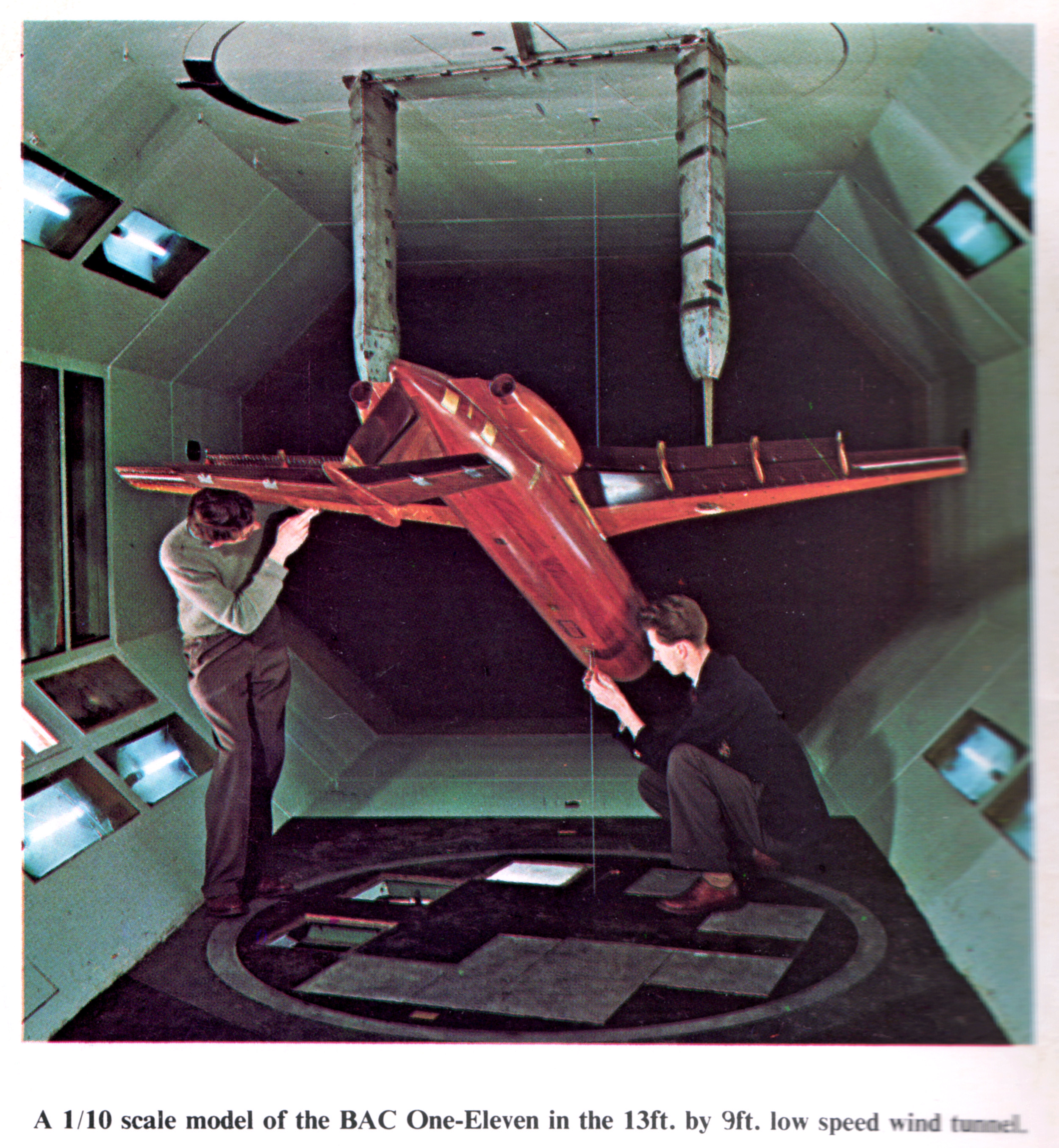
The 13ft. x 9ft. low speed tunnel, together with the high subsonic tunnel formed the early post-war expansion of the wind tunnel facilities, necessitated by the rapid development of aircraft during and since the war years.
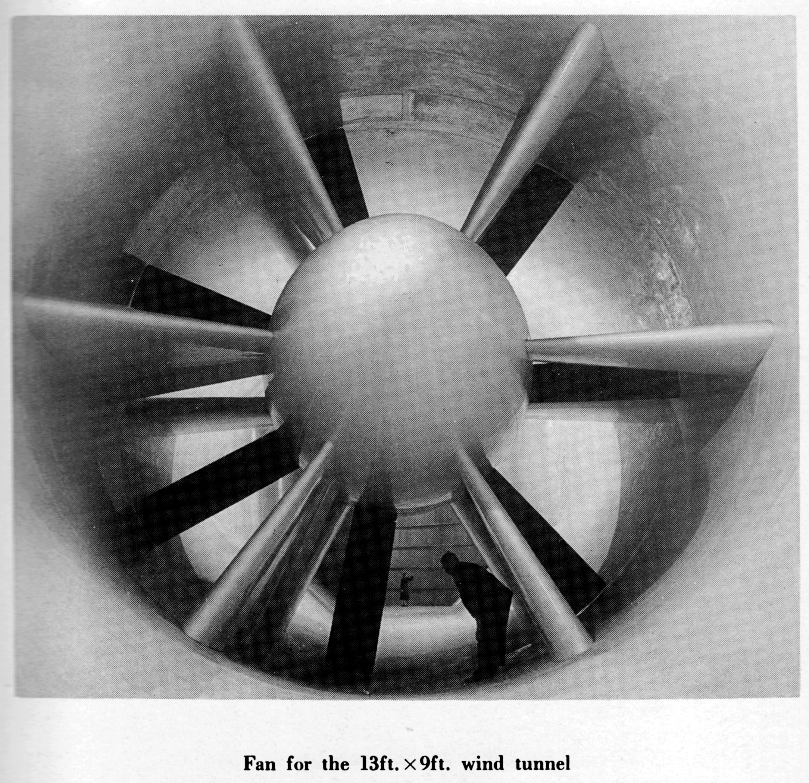
Although described as a low speed tunnel, the l3ft. x 9ft. is one of the fastest tunnels of its size. At the maximum working speed of 240m.p.h., 75 tons of air pass through the working section per minute. The tunnel is 220ft. long, has a contraction ratio of 10.8 to l, and is driven by a single 24ft. diameter seven-bladed fan, powered by a 2,200h.p. electric motor.
The resultant forces acting on the model are broken down into six components, and measured by a balance developed by the National Physical Laboratory.
To prevent interference with the air flow over the wing, the support struts from which the model is suspended must be as thin as possible. A compressive load requires a fatter strut than a tensile load, in order to prevent buckling. If the Weight of the model and the lift developed by its wings both act downwards, the strut will always be in tension so to this end, the models are hung upside down. This also necessitates mounting the balance, used to measure the forces acting on the model, above the Working section.
The size of the working section enabled us to test a
1/5 th scale Scimitar Naval fighter,
1/10th scale Viscount 800,
1/12th scale Vanguard,
1/15th scale VC10,
1/13th scale Valiant
1/10th scale One-Eleven.
This tunnel is also equipped with large suction and Compressed air plants for testing modern high lift devices, such as blown flaps.
Test Reynolds Numbers of about 3 million are achieved.
The high subsonic tunnel has a working section of 3ft. by 2ft. and utilises a two-stage fan powered by a 2,000h.p. electric motor. Test Reynolds numbers range from 1 to 2 million as the Mach numberincreases from 0.4 to 0.94(715 mph) at a working pressure of half an atmosphere.
As the air speed in the tunnel increases so does its temperature. At the higher speeds reached in this tunnel the heating effects are appreciable and cooling is by air exchange. The average running temperature of the air is about 30° above atmospheric.
Some of the work is carried out on "half models" mounted on a four component balance which electrically transmits the magnitude of the forces to automatic data handling equipment.
The "half models" are used to attain a larger Reynolds Number and scale and thus more accurate results. Full models can be mounted on a "sting"-see picture of supersonic tunnel-and tested, but to obtain accurate results from the smaller scale models is very costly.
Both this tunnel and the supersonic tunnel are equipped with Schlieren apparatus which is used to demonstrate visually the air around the model. The Wind Tunnel Department forms an important part of the Aerodynamics Section of the Design Organisation.
It gathers aerodynamic data by means of models both before and after aircraft projects reach the design stage. As the design advances, testing becomes increasingly detailed, and the accuracy required is such that models may cost £10,000 or more.
At Weybridge there are five wind tunnels covering the entire speed range up to Mach 3, 5, and the Department also has access to the Vickers-Armstrongs (South Marston) Ltd. , tunnel at the former Supermarine Works.
As a member of the Aircraft Research Association, Vickers-Armstrongs (Aircraft) Ltd., also uses the A.R.A. facilities including the Mach l.4 - 4,0 supersonic tunnel and the Mach 0.6 - 1,4 transonic tunnel.
The foundation of BAC means that the new high speed wind tunnels at Warton are available to the group.
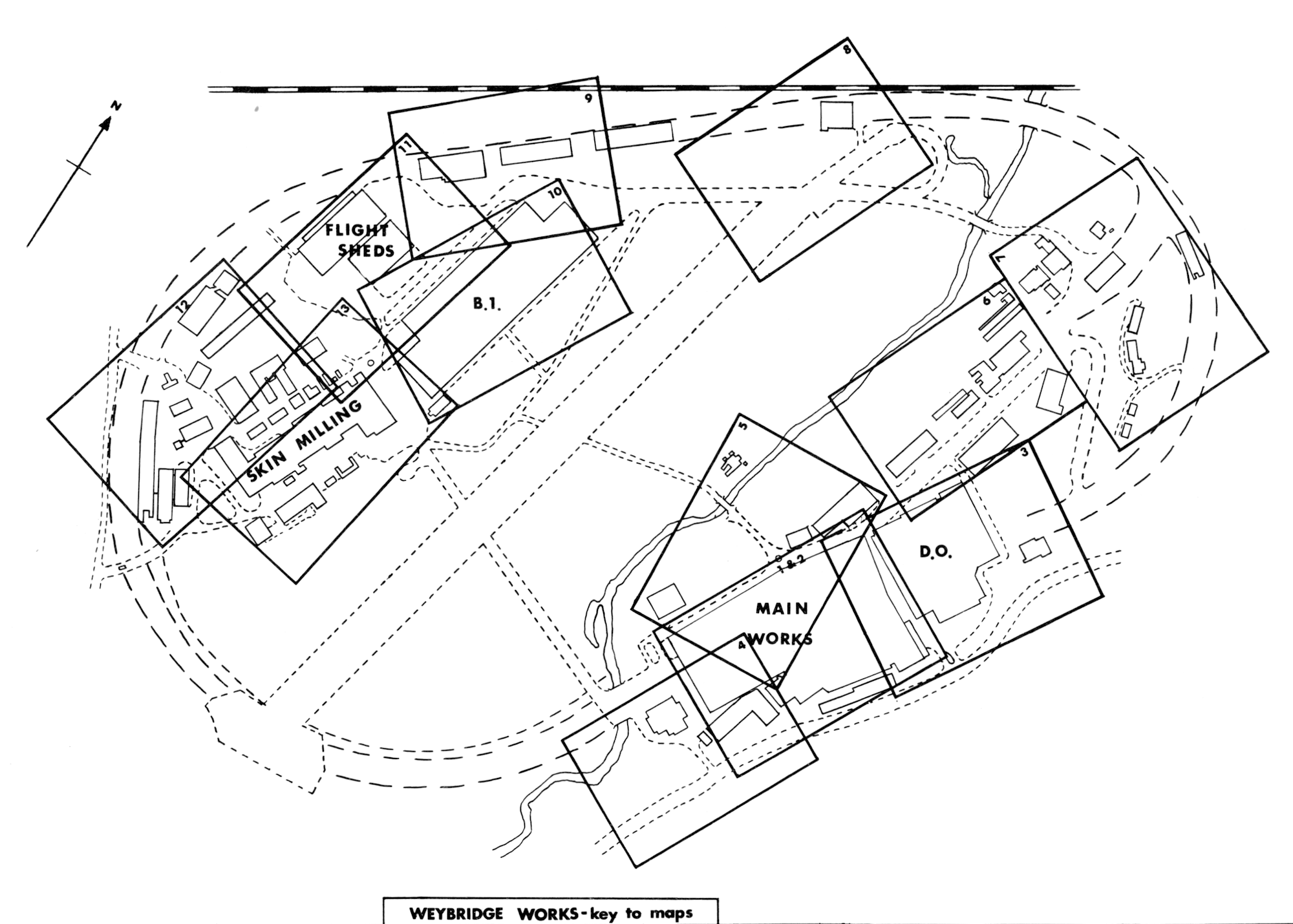
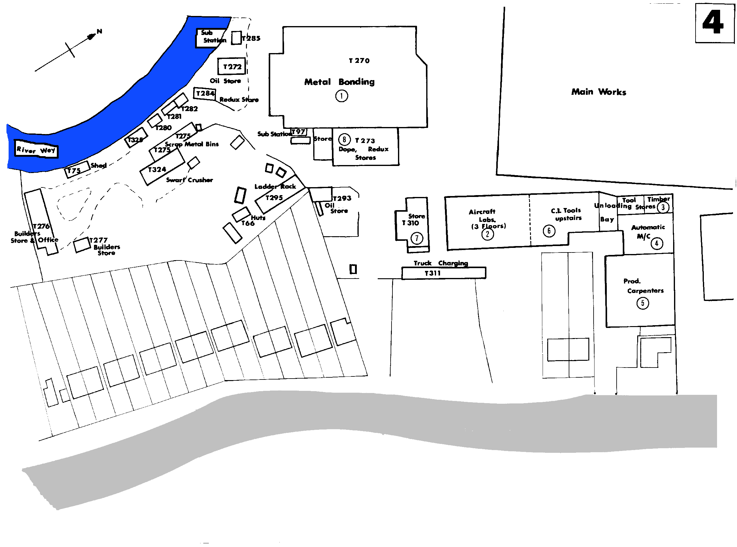
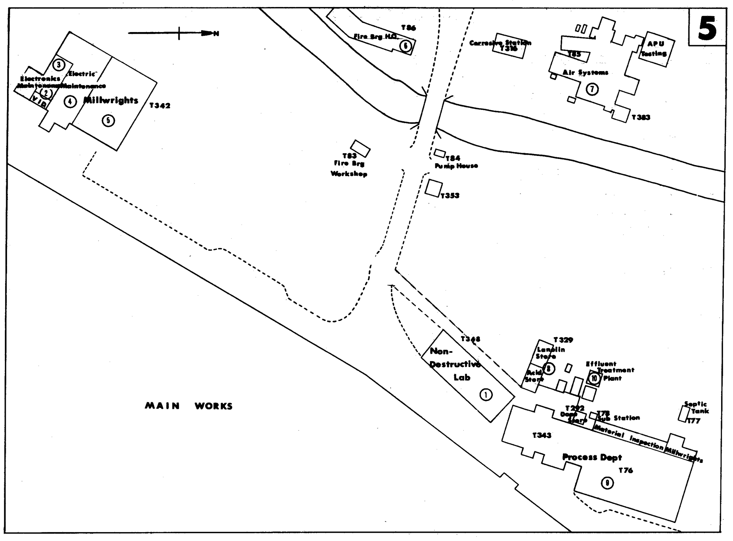
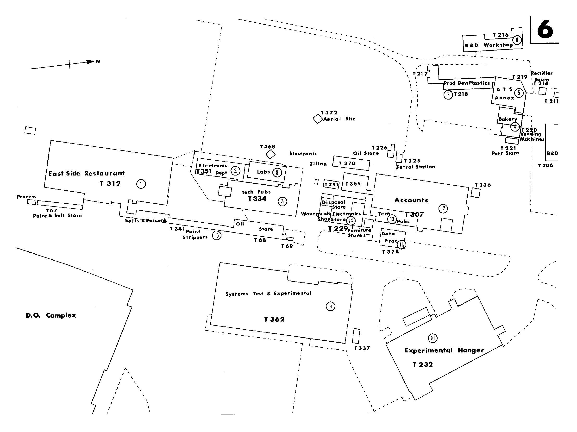
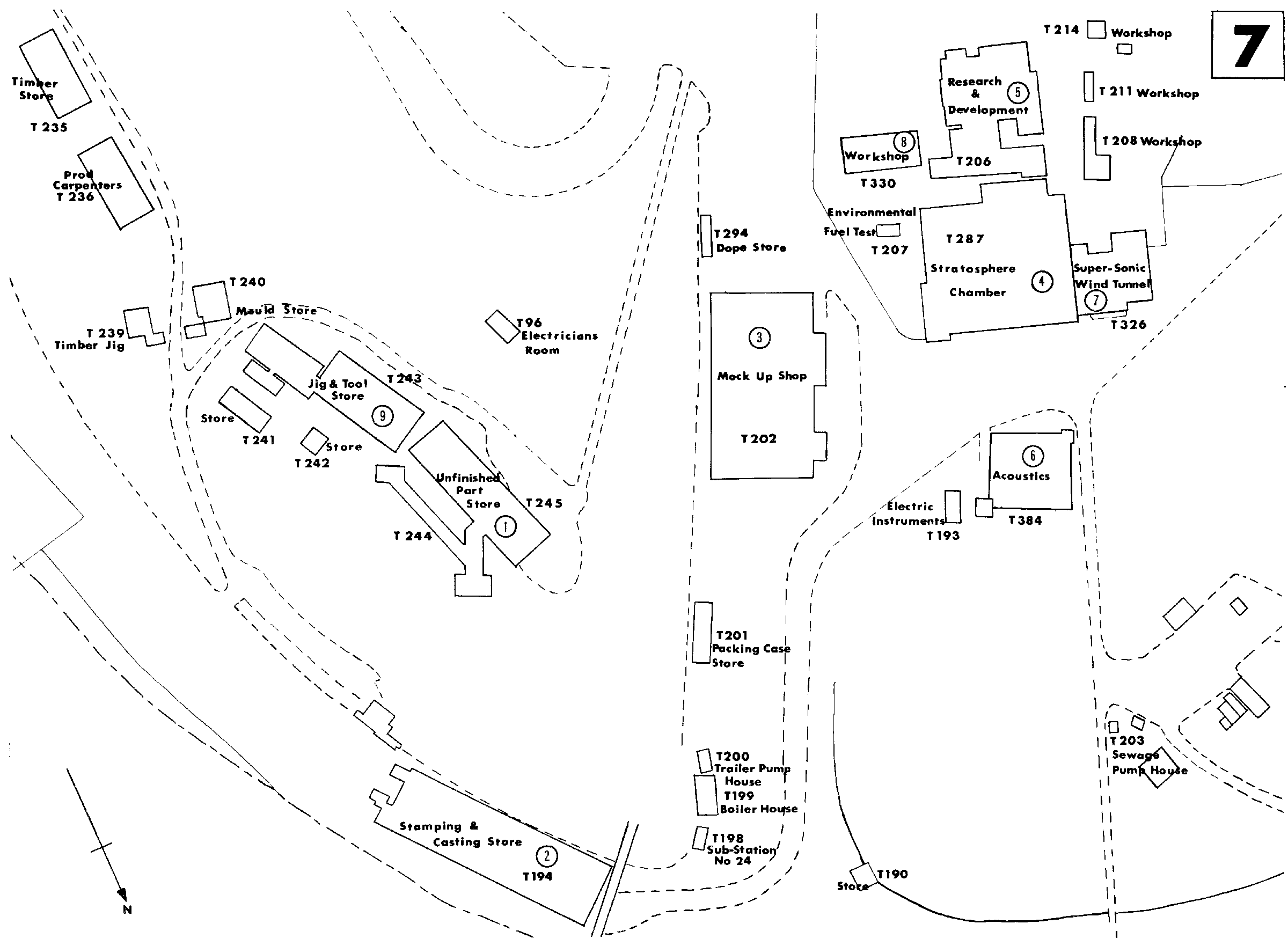
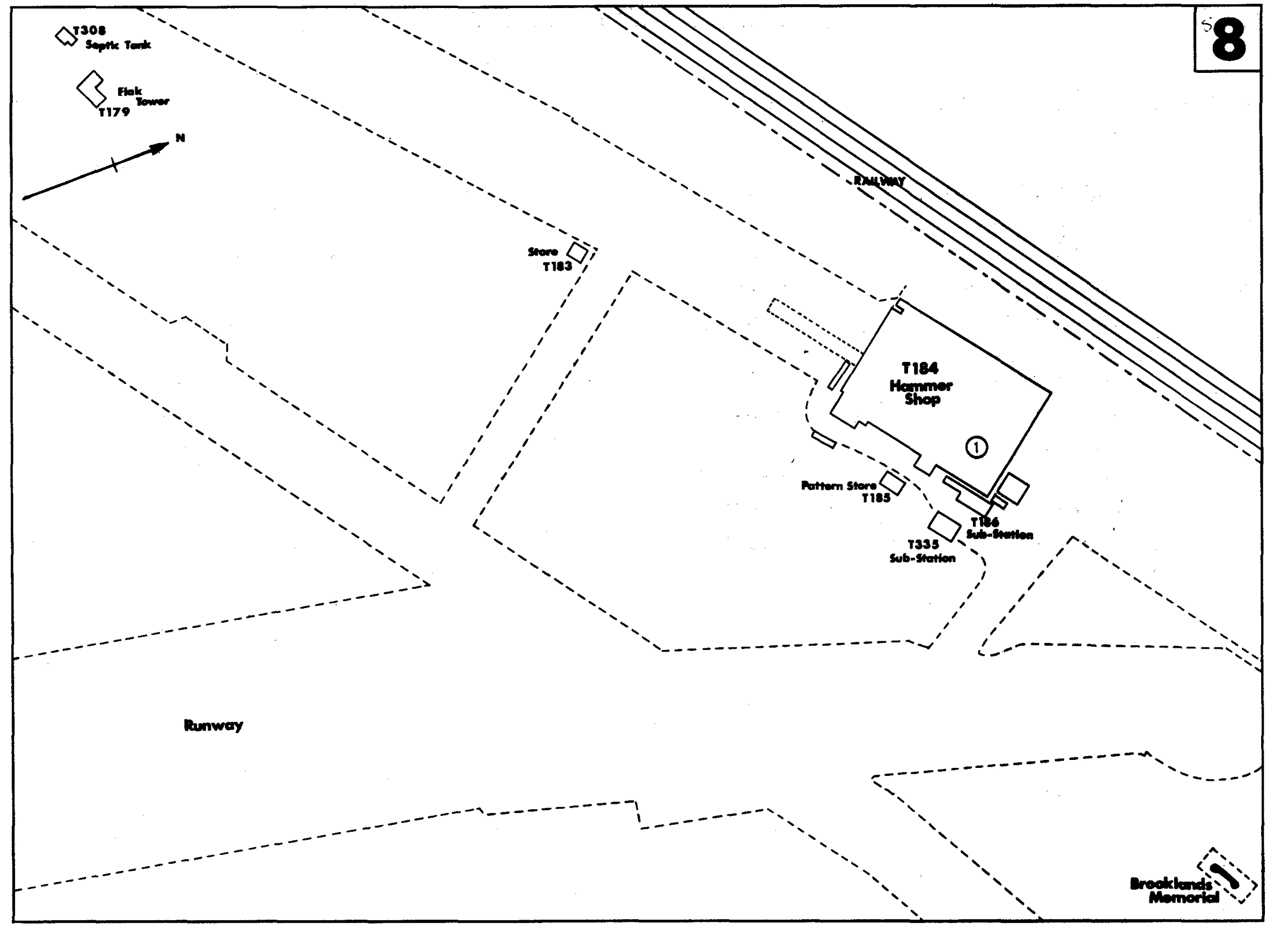
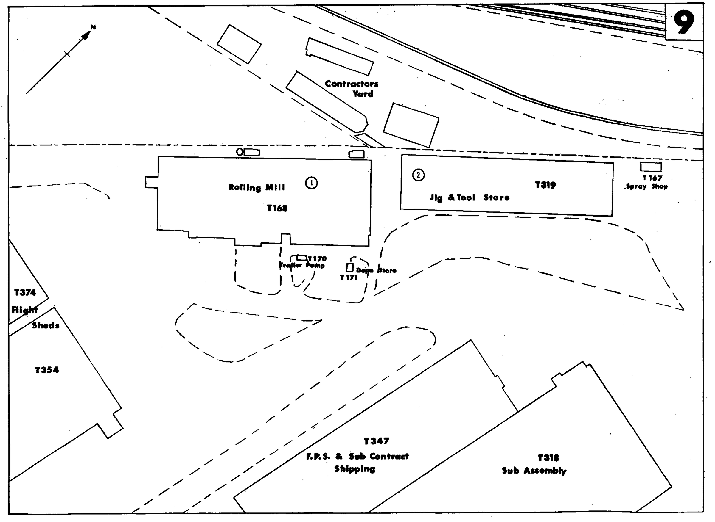
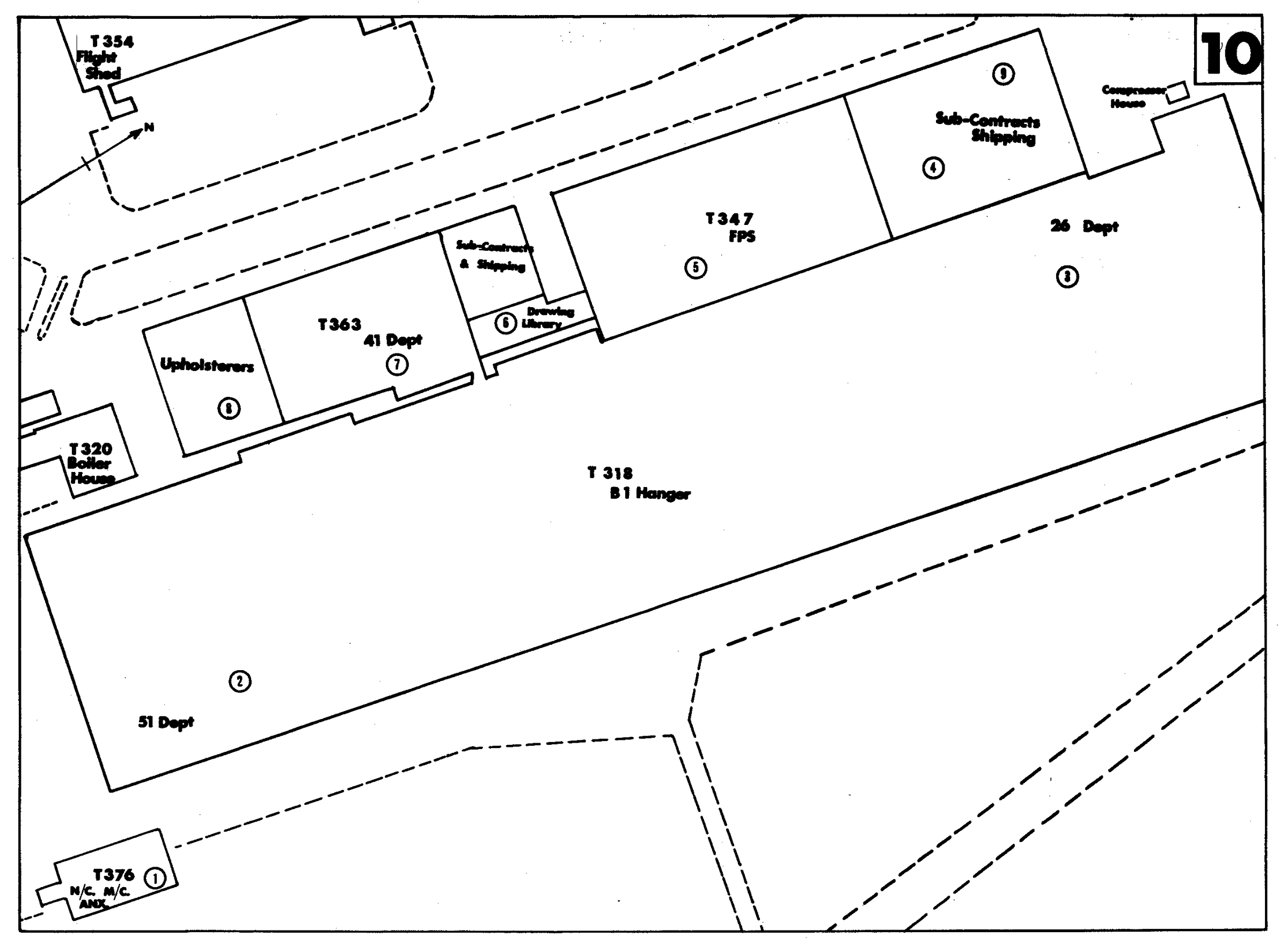
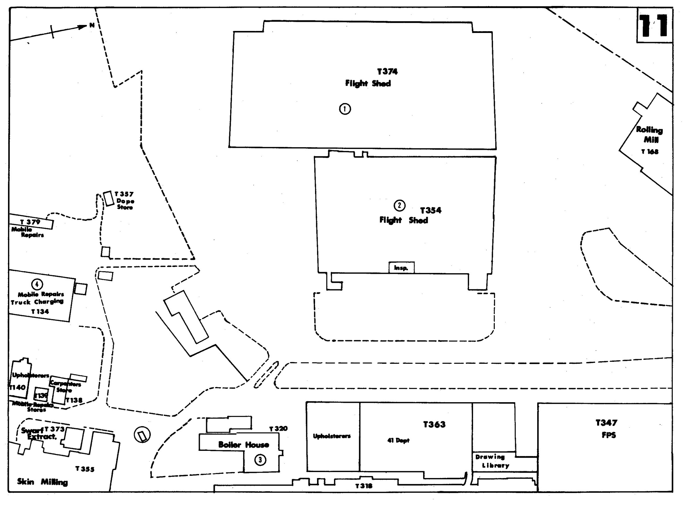
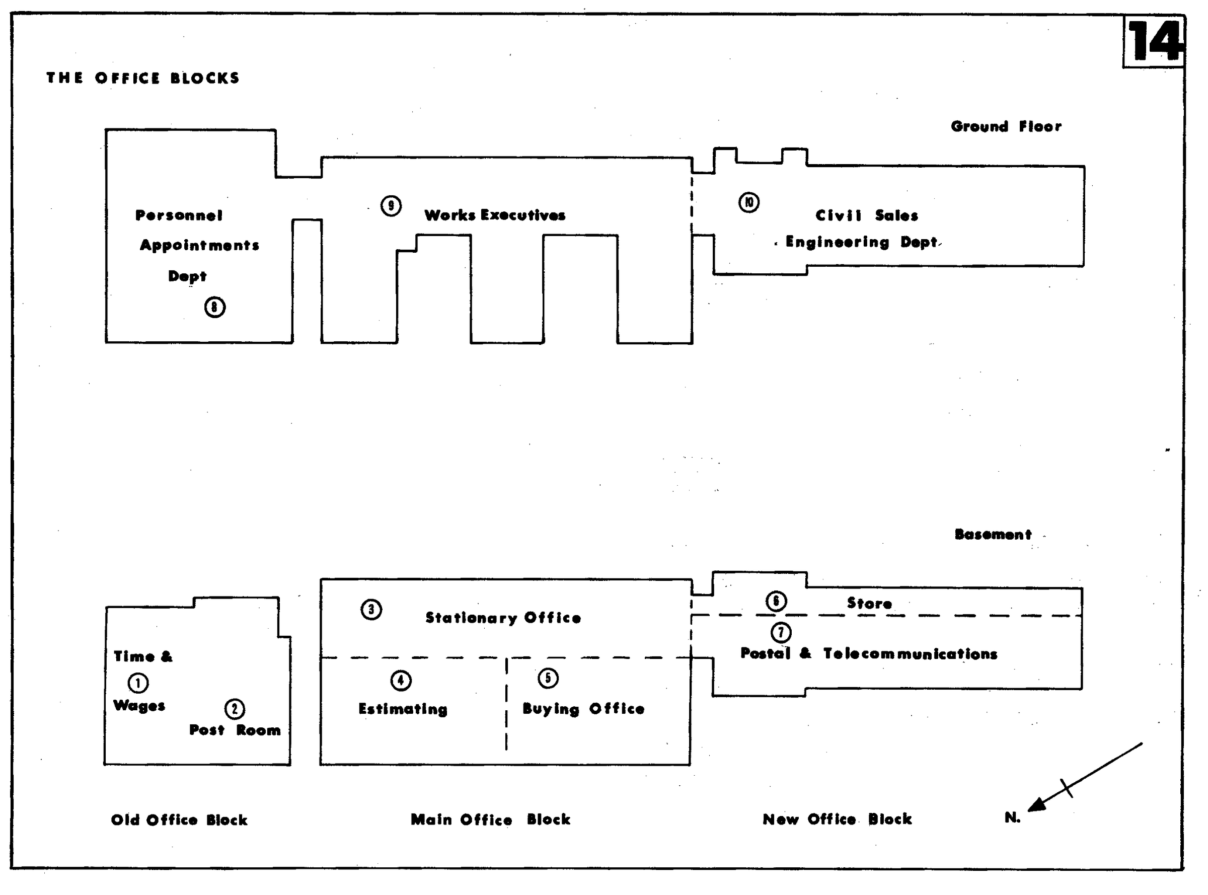
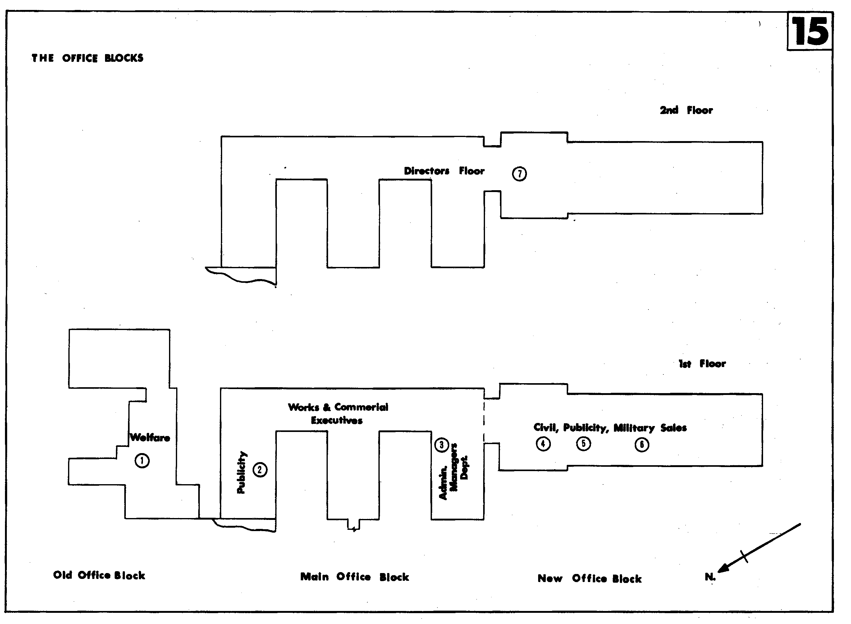
Maps
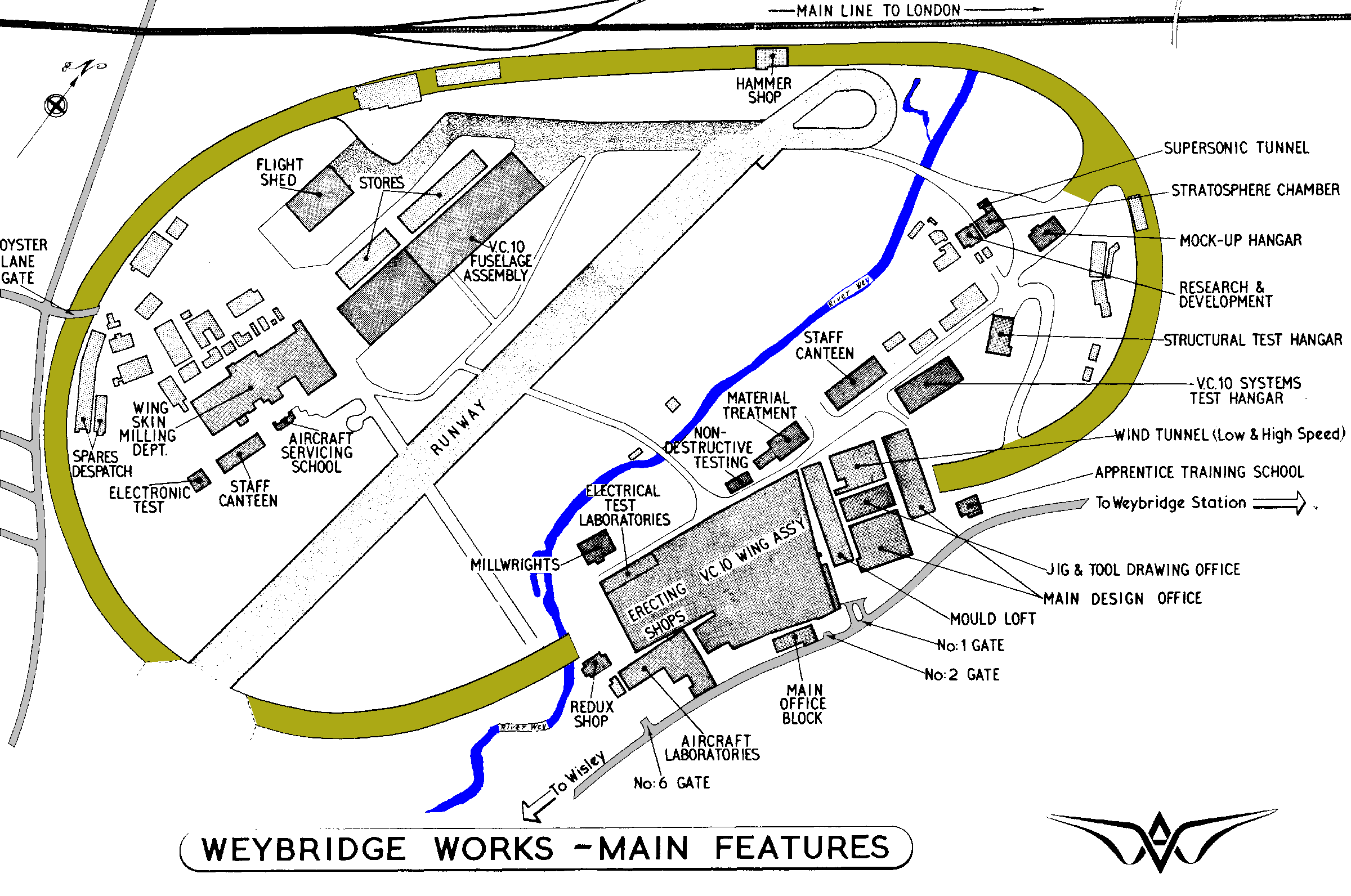
Prepared by the Administration Manager's Department as a
reference guide to the manufacturing facilities of the
British Aircraft Corporation Ltd. (Weybridge Division).
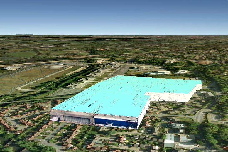
My work is also on Google Maps, here you can see locations of the various
1968 departments superimposed on a modern Google map.
http://goo.gl/maps/RUcZ5

Maths in 1960's
Practical Maths in 1960's (before computers)
In the training school and at college we learned how to Screw Cut on the lathe. One would check the size with an appropriate nut, which worked but was it right? In the factory they had posh thread gauges. In the R&D workshop precision was the thing and that meant maths. To check a screw thread you put three small wires in the thread two at one side the third opposite and measured over the wires with a micrometer. Two formulae had to be worked on one to calculate the best wire size, then I obtained 3 very small twist drills from the stores.
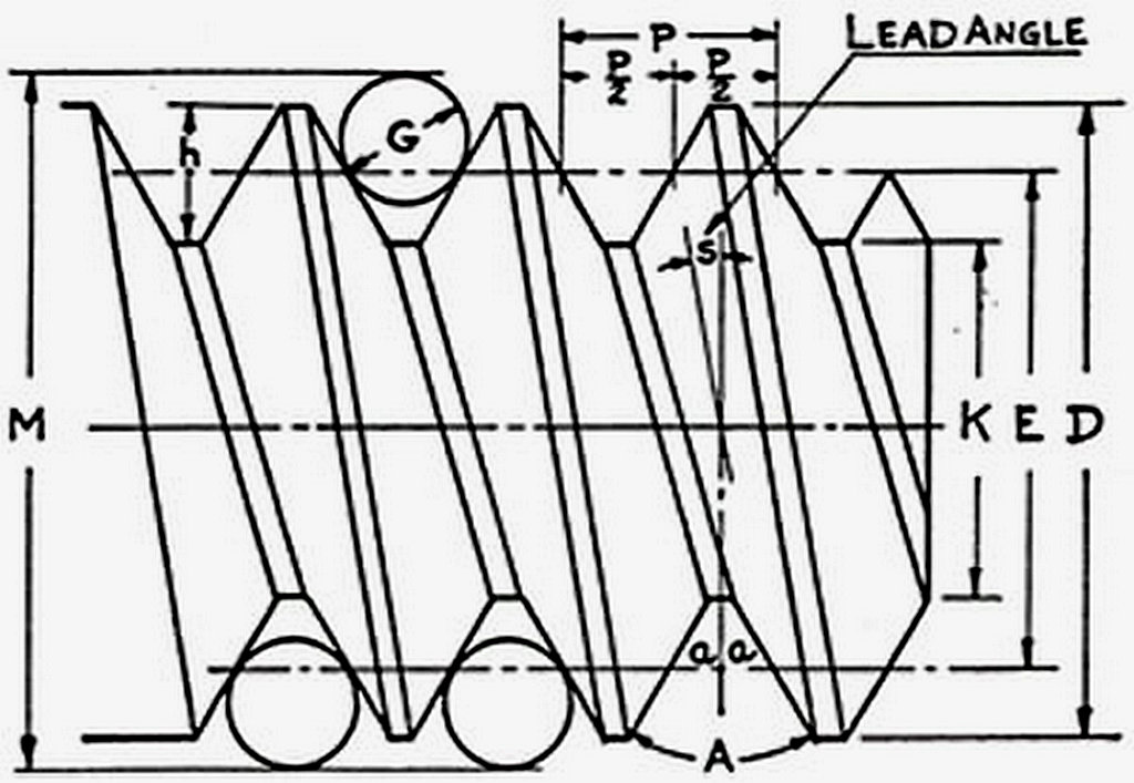
I used the actual drill size in another formulae to calculate the desired measurement over the wires (M). The only aid I had then was 4 figure log / trig tables. Square Root = Find Log using the table, divide by 2 then find the Antilog.
Oh by the way one also had to look at the VP book (Vickers Process) for thread truncation etc. Something I had not learned of before.
OK I could do it, I passed O Level maths but how I just can't remember. Here I am now 50 + years later with a calculator, a computer, a spreadsheet, the internet and it is all so easy.
Later on in the Wind tunnel I worked on a G sip Jig Borer.
Working on that Jig Borer say two meters long and to three places of metric decimals required more than 4 figure tables. So we had a 7 figure log tables and the super calculator of its day, the Brunsvega, a mechanical calculator.
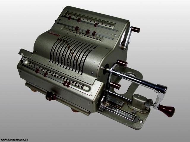
To calculate a square root in a simple right angle triangle calculation (Pythagoras) John and I would have a race. One would use 7 fig logs the other the Brunsvega. Up to five minutes later one of us would have an answer. The method is described here It was based on the formula that the sum of the first n odd integers is n squared.
A      B       C
1      1       1
2      3       4
3      5       9
4      7      16

A :-  n
B :-  Odd numbers
C :-  Sum of odd numbers

Oh look A is the square root of C
Why oh why didn't the draughtsman put the dimension on the drawing? Because he did not know how we would set the work, that was the planners job. The planning sheets that we received just said, "Make complete".
We were paid top money and on shift pay (+ 20%) but the planner was paid more to write "Make complete"!
The drawing office also had the same type of thing but they had 12 fig logs and their calculator had motors!
One job of note was a checking fixture for the Rolls Royce RB 211 jet engine. We had a RR inspector with us, we worked the maths he checked it we set the machine he checked it. Then we could cut metal !
Still later in 1971 I worked in a petrochem instrument factory initially the maths were done using a slide rule. Then a new desktop electronic calculator arrived, just a calculator (nixie tubes not LED) but it did do square roots.
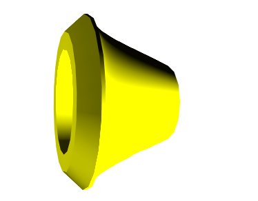
This drawing of a flow meter control cone represents about three years of my work some fifty years ago, 1971. Two hundred coordinates were required and all had to be calculated on the new machine.
Today the drawing and the calculations took less than 15 minutes. My how things have changed. MS Excel is thought by some to be an accountants tool, which of course it is.
Engineers however should now think of Excel as their trusty calculator.
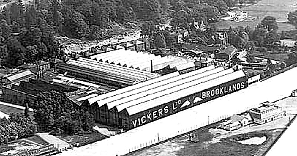
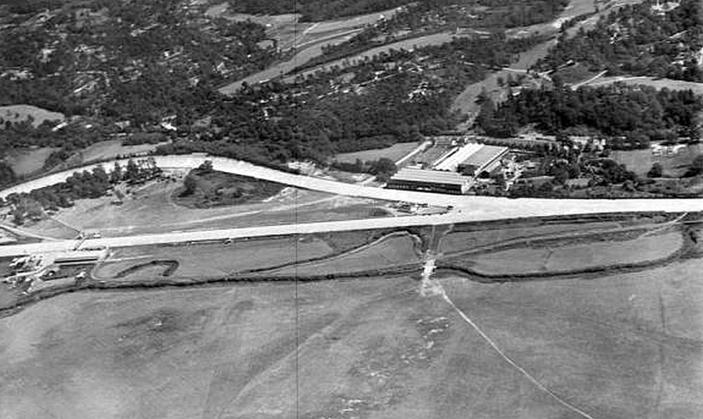
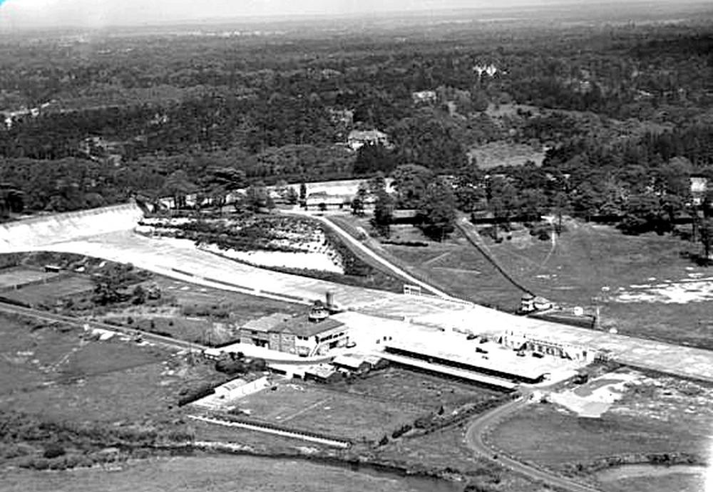
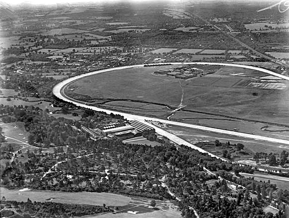
A few Photographs
From various sources, some my own, some my Father's others well, who knows where?
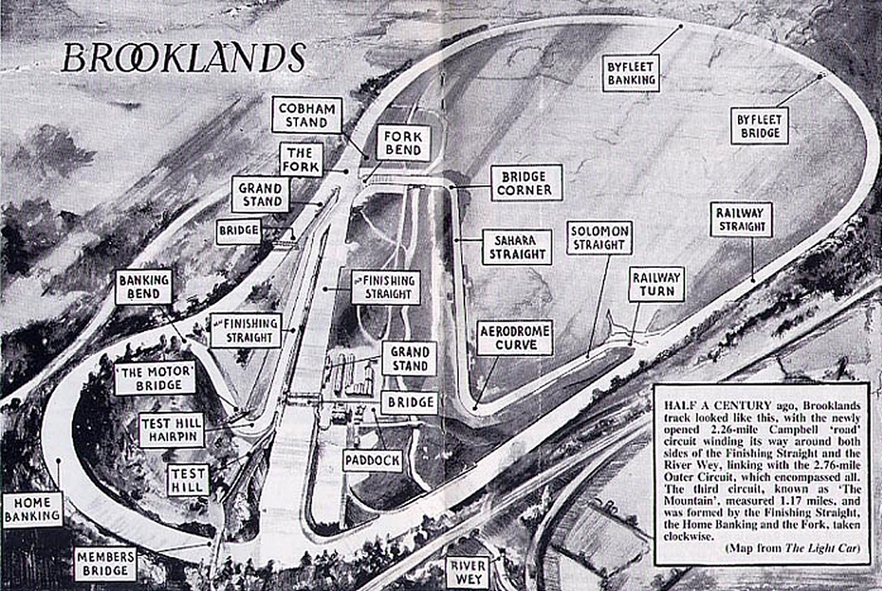
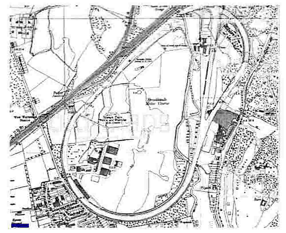
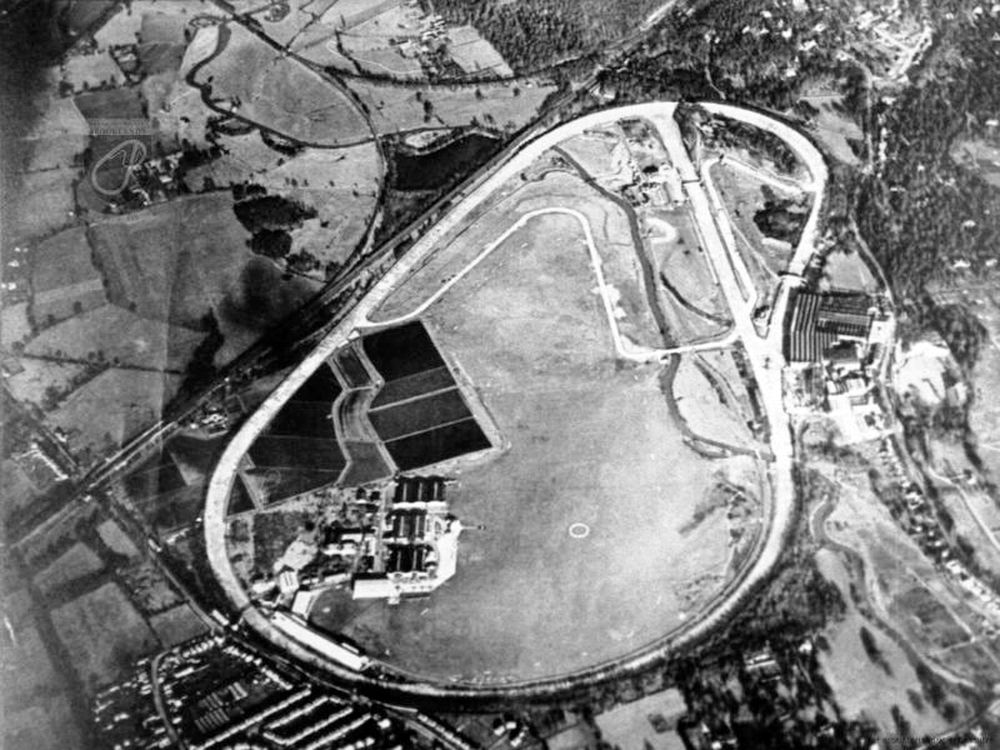
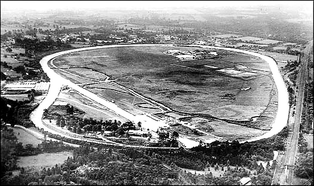
--- END ---
19 April 2024